
6-Band Graphic Equalizer circuit
The EQ-2 circuit functions by dividing the audio frequency spectrum into six distinct bands, allowing for precise control over the tonal quality of the audio signal. Each band features a dedicated fader, which enables the user to adjust the gain for that particular frequency range. The faders provide a visual representation of the adjustments made, facilitating easier manipulation during audio mixing or sound reinforcement.
The circuit typically employs operational amplifiers (op-amps) in a band-pass filter configuration for each frequency band. The design ensures that only the desired frequency range is affected by the adjustment of the corresponding fader. The flat gain position at the center of the fader ensures that the audio signal remains unaltered when no adjustments are made.
For the implementation of stereo operation, two identical EQ-2 circuits are used, one for the left audio channel and one for the right. This configuration maintains the stereo image and ensures that both channels can be equally adjusted to achieve a balanced sound output.
The EQ-2 circuit is suitable for various applications, including home audio systems, professional sound reinforcement, and recording studios. Its flexibility and user-friendly interface make it a valuable tool for audio engineers and enthusiasts seeking to enhance their sound mixing capabilities.The EQ-2 it is a circuit of graphic equalizer 6 band of regulation. Each band is regulated from the potesometers RV1-6, that are, for better optical indicate of regulations, Fader. This does not mean that we cannot him replace with simply potesometer. In the center of regulation potesometer, the gain is null (flat), but in terminal has +/- 15 db, boost or cutting off, respectively.
For stereo operation, it will be supposed two times.. 🔗 External reference
Related Circuits
This RS232 power supply circuit diagram is a simple RS-232 line driver power supply that operates from an input voltage as low as 4.2V and delivers an output of ±12V at ±40 mA with an efficiency of better than...
A collection of touch switch circuits is presented. A touch switch is an electronic device that allows control of a circuit simply by touching a sensor. The circuit diagram illustrates a simple design that utilizes only eight components. The...
A sine wave oscillator can be implemented using a Wien-Bridge oscillator, similar to the previous sine wave oscillator circuit; however, another method is now presented. The Wien-Bridge oscillator is a type of electronic oscillator that generates sine waves. It is...
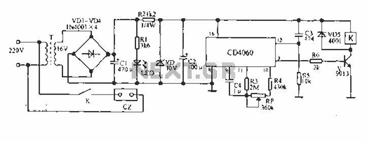
A CD4060 production time controller circuit is illustrated below. It is connected in such a way that R5 and C3 form a differential circuit to create a delay time from the start. Under the influence of the oscillating signal,...
This circuit is primarily designed to provide a microphone input for standard home stereo amplifiers. Utilizing a battery supply effectively eliminates the risk of low-frequency hum interference from mains power, simplifying the connection to the amplifier by removing the...
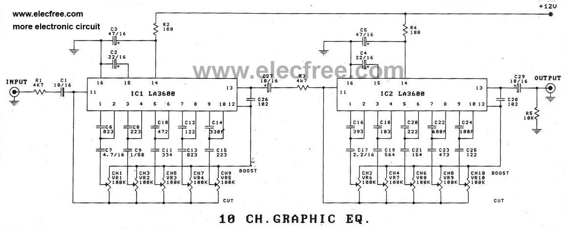
In addition to using the LA3600 IC, a 5-channel graphic equalizer can also be designed as a 10-channel graphic equalizer circuit through appropriate connections. The design of a 10-channel graphic equalizer circuit utilizing the LA3600 integrated circuit (IC) offers enhanced...