
0.1 To 90 second timer
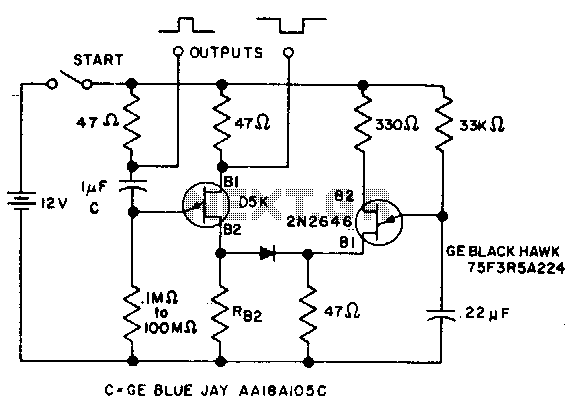
The circuit operates by initiating a timer interval upon the application of power, which is critical for timing applications. The 2N2646, a silicon NPN transistor, functions as a key component in the oscillator circuit. It is responsible for generating a square wave signal by rapidly switching on and off, which is then fed to the base of the D5K. The D5K, likely a type of digital logic IC or a similar device, responds to these pulses to control its output state.
The reduction in effective inductance (L) of the D5K is a significant design consideration. By manipulating the inductive characteristics, the circuit allows for a larger timing resistor, which can increase the timing interval as needed for specific applications. Concurrently, the ability to use a smaller timing capacitor is advantageous as it reduces the overall size of the circuit and can enhance performance by minimizing leakage currents and improving response times.
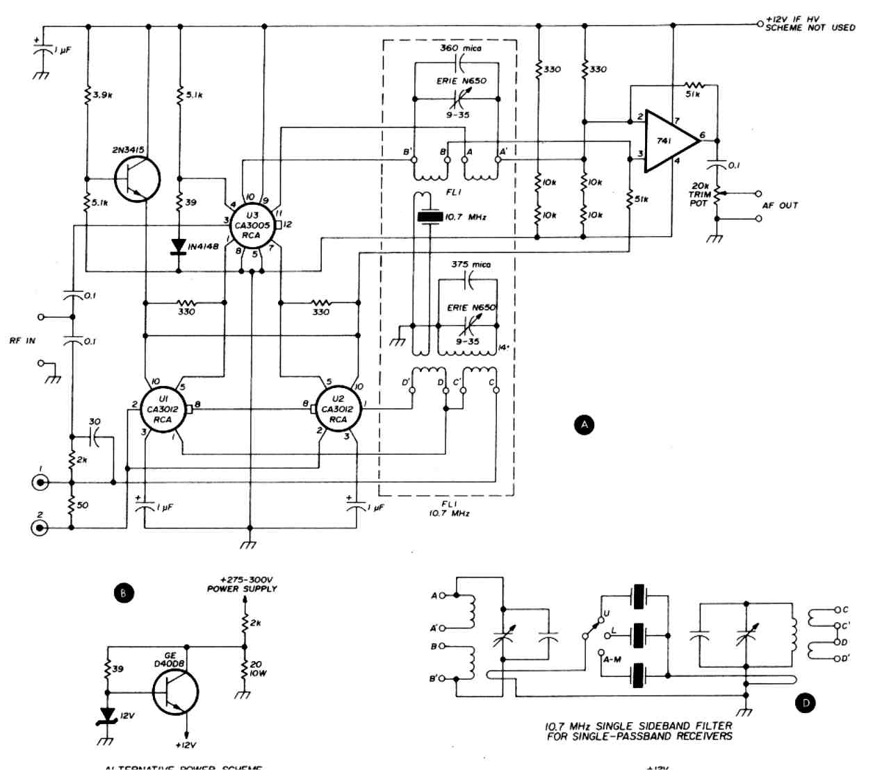
In practical terms, this means that the circuit can be tailored to achieve longer timing intervals without requiring large physical components, which can be a limitation in compact electronic designs. The design can be further optimized by selecting appropriate resistor and capacitor values based on the desired timing characteristics, ensuring efficient operation within the specified application parameters. Overall, this circuit exemplifies an effective use of component characteristics to achieve desired timing functions in electronic systems.The timer interval starts when power is applied to circuit and terminates when voltage is applied to load. 2N2646 is used in oscillator which pulses base 2 of D5K This reduces the effective L of D5K and allows a much larger timing resistor and smaller timing capacitor to be used than would otherwise be possible. 🔗 External reference
Related Circuits
This circuit includes a Relay Timer Circuit. One of the most commonly used circuits is that of the 555 Timer integrated circuit (IC). The circuit is designed to control a relay based on a timing interval. The Relay Timer Circuit...
This is a programmable clock timer circuit that utilizes individual LEDs to display hours and minutes. Twelve LEDs can be arranged in a circular pattern to represent the 12 hours on a clock face, while an additional 12 LEDs...
A dancing light can be easily constructed using a 555 timer wired in astable mode. This circuit alternately blinks two LEDs with a certain delay and can be modified to include additional LEDs or to control incandescent lamps. The...
The reciprocating detector was designed by R. S. Badessa at MIT. The RD features a carrier-synthesized reference signal and requires no external beat frequency oscillator (BFO). The circuit offers advantages over conventional detectors by automatically adjusting its BFO level...
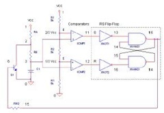
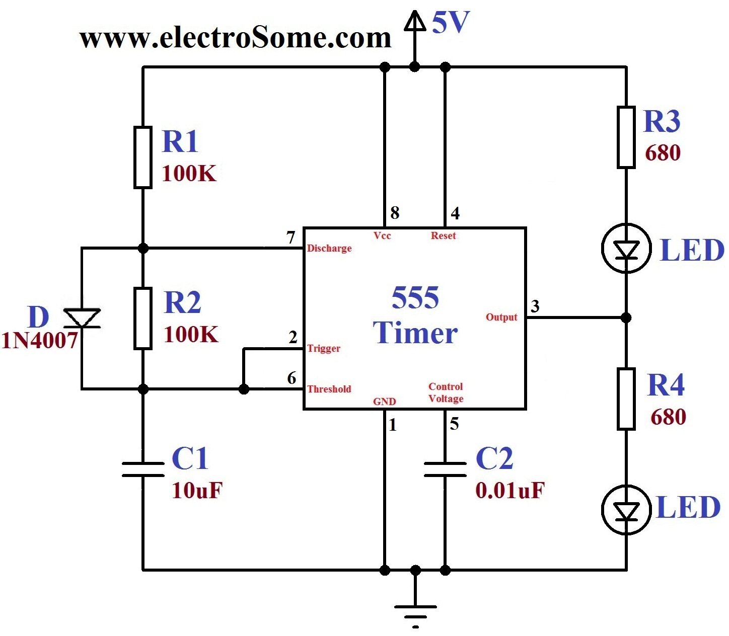
The 555 Timer IC operates in three modes: monostable, astable, and bistable/Schmitt trigger. This article will focus on its astable mode. The astable mode of the 555 Timer IC is characterized by its ability to generate a continuous square wave...
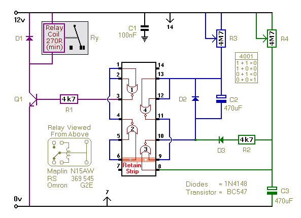
This timer utilizes a basic monostable circuit. The duration for which the relay remains energized, referred to as the ON period, is regulated by the resistor R3 and capacitor C2. Conversely, the duration for which the relay remains de-energized,...
Warning: include(partials/cookie-banner.php): Failed to open stream: Permission denied in /var/www/html/nextgr/view-circuit.php on line 713
Warning: include(): Failed opening 'partials/cookie-banner.php' for inclusion (include_path='.:/usr/share/php') in /var/www/html/nextgr/view-circuit.php on line 713