
second generation reciprocating

The schematic of the reciprocating detector MKII, utilizing wideband-amplifier ICs, illustrates the circuit's layout and functionality, demonstrating the advancements made in this design iteration.The The reciprocating detector was designed by R. S. Badessa at M. I. T. The RD features a carrier-synthesized reference signal and requires no external bfo. The circuit offers advantages over conventional detectors in that it adjusts its bfo level automatically in proportion to the average signal level received. First introduced in ham Radio in March, 1972, the RD has gone through several metamorphoses. The version presented here uses ICs and can be used in modern receivers using semiconductors. Also included is a design for a 10. 7-MHZ ssb filter for single-passband receivers. Editor. During the past three years I`ve had many requests for revisions to the reciprocating detector circuit so that it can be used directly at high frequencies. Here`s an updated IC design that can be used at frequencies up to 20 MHz. required very careful circuit layout to reduce or eliminate inter-circuit coupling, and in particular to maintain the correct phase relationship required in the feedback loop.
Also, the detector portion operated as a half-wave rectifier. A current-regulating source had to be adjusted to cause the signal diode to operate at a level just below conduction, so that at frequencies above 5 MHz the diode and its circuitry ceased to perform uniformly. Result - a badly distorted detected signal. Despite the distortion, in some cases the circuit performed well enough for signal identification. But much was to be desired. A cure for individual cases was to adjust the bias level for the current-source diode until it just conducted on noise.
In most cases, with a tube receiver that produced i-f signals to the RD input exceeding the saturation level of the complete circuit, a clipped response occurred. Single sideband signals then became unmanageable because of widely varying signal levels that couldn`t be controlled by the agc systems in older tube receivers.
The original circuit was designed to be used in receivers such as the Collins 5151 and Drake R4A, which have highly selective dual or adjustable filters in the receiver i-f passband. In the 5151 receiver the i-f output was fed to the RD through a cathode follower; the maximum output level could not exceed 3 volts.
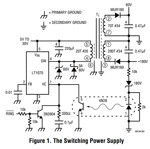
The application using the Drake R4A employed enough attenuation through the coupling to the original product detector output transformer to preclude saturation. An updated design, which uses ICs, allows the RD to be incorporated into more modern receivers. Models of the new circuit have been made for 10. 7, 16, and 20 MHz. Test models were constructed using point-to-point wiring. Later models used PC boards. The circuit consists of two amplifier chips, ICl, and IC2 (fig. 1). These are monolithic wideband amplifiers with frequency response between 10 kHz and 20 MHz. These chips are 10-lead devices in TO-5 cans. A third rf amplifier, IC3 is a balanced differential amplifier using an internal constant-current source, which eliminates the orignal problem caused by the biased half-wave rectifier.
This amplifier operates from 0-100 MHz. This wideband response allows the circuit to work in the same manner as the original current source for the detector and as the reciprocating switch. These two functions are improvements over the old circuit. The dynamic range improvement alone is worth the effort. Tracing the signal through the circuit, we see that a capacitive input circuit couples the rf signal into IC3 input.
The capacitive coupling isolates any direct current that might be superimposed on the rf signal from the i-f ouput circuit. The input signal is then applied to a phase-shift network, then to one set of inputs of IC1 and IC2. These three inputs are then provided with a signal path that`s essentially in series with the reference signal, or beat frequency similar to a conventional product detector.
fig. 1. Schematic of the reciprocating detector MKII using wideband-amplifier ICs, (Al. Also shown are an alt 🔗 External reference
Related Circuits
Here is a Tesla coil secondary design: Wind 750 turns of 24-gauge enameled magnet wire onto an 18-inch long piece of 1.9-inch outer-diameter PVC pipe. The large coil has an inductance of approximately 2800 mH and a self-capacitance of...

This circuit provides a visual 9-second delay using a 7-segment digital readout LED. When the switch is closed, the CD4010 up/down counter is preset to 9, and the 555 timer is disabled with the output held high. The circuit utilizes...
This precise one-pulse-per-second clock is constructed using a few common components and is driven by a 50 or 60 Hertz mains supply, without any direct connection to it. It produces a beep or metronome-like click and/or a visible flash...

This precise one-pulse-per-second clock is constructed using a few common components and is driven by a 50 or 60 Hertz mains supply without a direct connection to it. An audible beep or a metronome-like click, along with a visible...
Here is a design that you can own, tailor to your specific needs, layout on your circuit board and put on your bill of materials. Finally, you will be in control of the black magic (and high voltages) of...
Power demand in portable designs can require, in specific applications, more than 1 A. A method involves paralleling two DC to DC converters on the same load instead of using a single higher current converter with a lower switching...