
dancing light using 555 timer
This circuit operates effectively in a variety of applications, including decorative lighting, indicators, and simple automated control systems. The 555 timer's versatility allows for easy adjustments to the frequency and duty cycle of the output signal by changing the values of the resistors and capacitor in the RC network. The inclusion of additional LEDs or the use of different types of loads, such as incandescent lamps, expands the potential applications of this circuit.
When implementing this design, careful consideration should be given to the power supply voltage and the current ratings of all components to ensure reliable operation. For instance, when using higher supply voltages, it is crucial to ensure that the 555 timer and any connected components can handle the increased voltage without damage. Additionally, when using the circuit to control larger loads through a relay, it is important to select a relay with appropriate ratings for the voltage and current of the load to be switched.
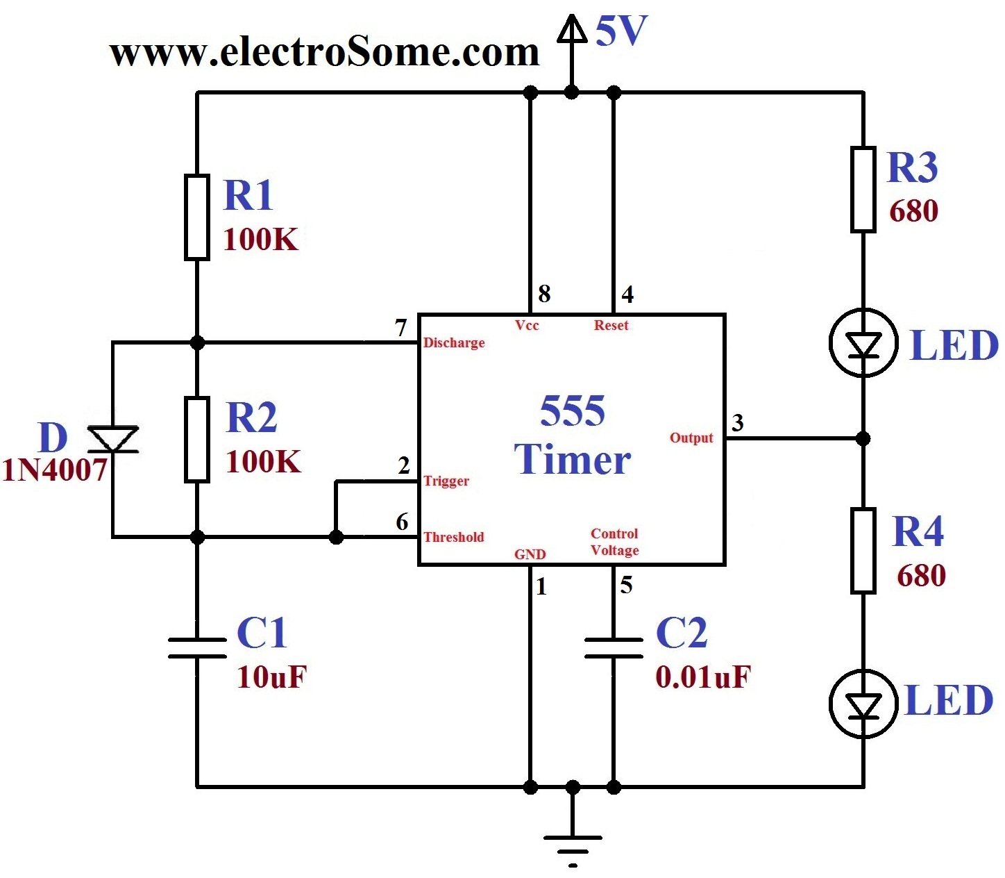
Overall, this dancing light circuit exemplifies the practical use of the 555 timer in creating dynamic lighting effects and controlling various types of electrical loads, demonstrating its utility in both hobbyist and professional electronic applications.A dancing light can be easily constructed using a 555 timer wired in astable mode. Please read the article Astable Multivibrator using 555 Timer before continuing. This circuit blinks two LEDsalternativelywith some delay and it can be easily modified to include more LEDs or for controllingincandescentlamps. Time period of oscillation is determined by RC time constant of the circuit. 1st and 8th pins of 555 timer are used to provide power, Vcc and GND respectively. 4th is the Reset pin which is a active low input and is tide to Vcc to avoid accidental resets. 5th is the Control Voltage pin which is not used in this application, hence it is grounded via 0. 01 F capacitor to avoid high frequency noises. When the output is HIGH capacitor charges to Vcc via resistor R1 and Diode. When the output is LOW capacitor discharges via resistor R2 and Discharge pin (7th) of 555 timer. When the output is LOW (0V) upper LED glows and when the output is HIGH (5v) lower LED glows. Instead of current limiting resistors R3, R4 you may use another LED, such that two LEDs will come in series. You can use higher supply voltages if you need to drive more LEDs. LM/NE555 can work upto 16V and SE555 can work upto 18V. 555 can source or sinkup to200mA current, if you need more current use a transistor driver. You can also connect this circuit to relay for controllingincandescentlamps as shown below. Here transistor is wired as a switch, when the base input is HIGH transistor turns ON and therelayisenergized.
Since the output of the 555 timer is square wave, the relay energizes and de-energizes continuously. Incandescentlamps turns ON alternatively since they are connected to Normally Open (NO) and Normally Closed (NC) of the realy output. LED ON OFF period is determined by theresistorsR1, R2 and the capacitor C1. You can change these resistors or capacitors to adjust the time period and can be determined by the equation, T = 1.
1RC. 🔗 External reference
Related Circuits
This circuit will allow you to turn on any piece of equipment that operates on 115 volts AC. The receiver circuit is based on the Radio Shack infrared receiver module (MOD), part number 276-137. It is also available from...
The circuit utilizes the LM324 low-power operational amplifier, which consumes approximately 3mA of current. This low current draw ensures that the battery will not be adversely affected if the circuit remains connected for extended durations. The LM324 is a quad...
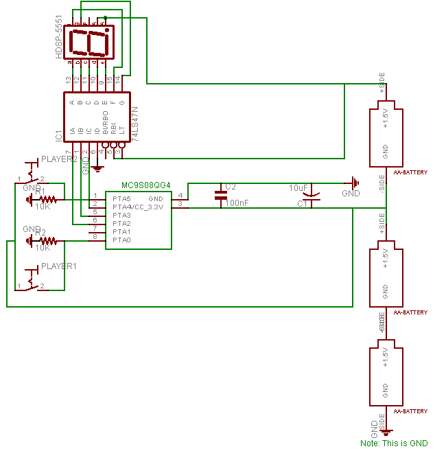
When the display shows "0," players must turn on their light switch as quickly as possible. The player who activates their light switch first is declared the winner. It is important to note that the display does not immediately...
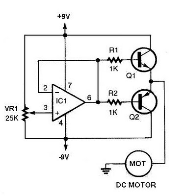
The speed increases in either direction as the potentiometer VR1 is adjusted toward its ends. The TIP3055 Q1 NPN power transistor has a collector current specification of 15A and a VCE0 rating of 60V DC. The MJE34 Q2 PNP...

This 555 timer circuit temperature monitoring system project can monitor temperature at up to four points. The system allows for the selection of whether the alarm should be triggered when the temperature increases or decreases, depending on the resistance...
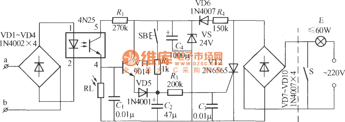
The diagram illustrates an automatic lighting control circuit activated by a telephone. At night, when the telephone rings or the user picks up the receiver, the light turns on. If the telephone stops ringing (when no one is listening)...
Warning: include(partials/cookie-banner.php): Failed to open stream: Permission denied in /var/www/html/nextgr/view-circuit.php on line 713
Warning: include(): Failed opening 'partials/cookie-banner.php' for inclusion (include_path='.:/usr/share/php') in /var/www/html/nextgr/view-circuit.php on line 713