
0-28V Variable power supply II

The described circuit employs operational amplifiers (op-amps) to create a regulated power supply with current limiting capabilities. The power transformer is designed with an additional secondary winding to provide a bipolar voltage of ±8 volts necessary for the op-amps to function effectively. This bipolar supply not only powers the op-amps but also allows for the generation of a reference voltage that can be adjusted below ground potential, enabling the output voltage to be varied down to zero volts.
Current limiting is achieved through the use of a small resistor, typically 0.2 ohms, positioned in series with the negative supply line. This resistor is crucial for sensing the voltage drop that corresponds to the current flowing through the circuit. As the load current increases, the voltage at the wiper of a 500-ohm potentiometer also rises. When this voltage matches or slightly exceeds the voltage at the non-inverting (+) terminal of the op-amp, the op-amp output transitions to a negative voltage. This action reduces the base voltage of the 2N3053 transistor, which in turn decreases the current flowing to the 2N3055 pass transistor.
The design allows for a current limiting range of approximately 0 to 3 amps, making it suitable for various applications. The power transistors, TIP32 and 2N3055, are required to be mounted on appropriate heat sinks to manage the thermal output effectively. The current sensing resistor should be rated for at least 2 watts to handle the power dissipation safely.
Heat generation in the pass transistor is a critical factor, calculated as the product of the voltage differential between the input and output and the load current. For instance, if the input voltage at the collector of the pass transistor is 25 volts, the output is set to 6 volts, and the load draws 1 amp, the heat dissipated by the pass transistor would be 19 watts. To mitigate excessive heating, the circuit can be configured to operate at an 18-volt setting, thereby reducing the dissipated power to approximately 12 watts. This careful consideration of thermal management is essential for maintaining the reliability and longevity of the power supply circuit.Another method of using opamps to regulate a power supply is shown below. The power transformer requires an additional winding to supply the op-amps with a bipolar voltage (+/- 8 volts), and the negative voltage is also used to generate a reference voltage below ground so that the output voltage can be adjusted all the way down to 0. Current limiting is accomplished by sensing the voltage drop across a small resistor placed in series with the negative supply line.
As the current increases, the voltage at the wiper of the 500 ohm pot rises until it becomes equal or slightly more positive than the voltage at the (+) input of the opamp. The opamp output then moves negative and reduces the voltage at the base of the 2N3053 transistor which in turn reduces the current to the 2N3055 pass transistor so that the current stays at a constant level even if the supply is shorted. Current limiting range is about 0 - 3 amps with components shown. The TIP32 and 2N3055 pass transistors should be mounted on suitable heat sinks and the 0.2 ohm current sensing resistor should be rated at 2 watts or more.
The heat produced by the pass transistor will be the product of the difference in voltage between the input and output, and the load current. So, for example if the input voltage (at the collector of the pass transistor) is 25 and the output is adjusted for 6 volts and the load is drawing 1 amp, the heat dissipated by the pass transistor would be (25-6) * 1 = 19 watts.
In the circuit below, the switch could be set to the 18 volt position to reduce the heat generated to about 12 watts. 🔗 External reference
Related Circuits

This circuit provides a regulated output of either 4.8 V or 7.2 V at a current of 15 mA, utilizing a 3 V input sourced from a bank of photocells. A load resistor (Rl) of 453 kΩ is required...
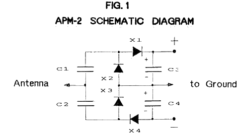
The Ambient Power Module (APM) is a straightforward electronic circuit that, when connected to an antenna and an earth ground, can deliver a low voltage output of up to several milliwatts. An optimal setup involves a long wire antenna...
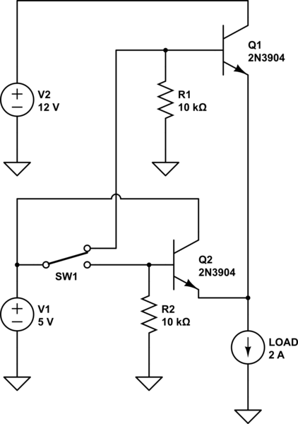
The project involves designing and constructing a breadboard power supply that draws power from an ATX-like switch-mode power supply (SMPS) using a 4-pin Molex connector. The design features a switch to select either a 12V or 5V output. However,...
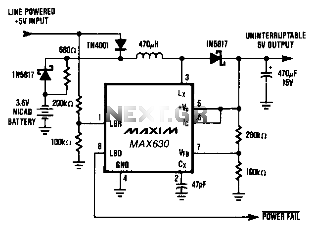
This circuit provides a continuous supply of regulated +5 V, with automatic switch-over between line power and battery backup. When the line-powered input voltage is +5 V, it supplies 4 A to the MAX630 and trickle charges the battery....
Occasionally, a low voltage power supply capable of delivering very high currents (hundreds of amperes) is required for applications such as spot welding, heating or melting metals, starting vehicle engines, or conducting various physical experiments. A decision has been...
This chapter presents detailed schematics for various power supplies compatible with commonly available Ar/Kr ion tubes in the surplus market. It includes examples of commercial designs such as the Omnichrome 150R and 532 head, Lexel 88 and head, alongside...
Warning: include(partials/cookie-banner.php): Failed to open stream: Permission denied in /var/www/html/nextgr/view-circuit.php on line 713
Warning: include(): Failed opening 'partials/cookie-banner.php' for inclusion (include_path='.:/usr/share/php') in /var/www/html/nextgr/view-circuit.php on line 713