
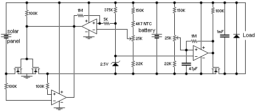
Solar Power Supply

The circuit operates by converting the variable voltage from the photocells into a stable output voltage. The photocells are connected in such a way that they can provide a maximum of 3 V under optimal lighting conditions. To ensure proper regulation, a voltage regulator is used, which is capable of stepping down the input voltage to the desired output levels of 4.8 V or 7.2 V.
The choice of load resistors is critical to achieving the specified output voltages. For a 7.2 V output, the use of a 453 kΩ resistor limits the current to 15 mA, ensuring that the circuit operates within its design parameters. Conversely, for a 4.8 V output, a 274 Ω resistor is employed, allowing for the same current flow while adjusting the voltage level.
The efficiency of the regulator, at around 70%, indicates that there will be some power loss in the form of heat. This factor is essential when selecting solar cells, as the input power must be sufficient to accommodate the losses while still providing the necessary output power. It is advisable to choose solar cells that can deliver more than 3 V under varying light conditions to ensure consistent operation of the circuit.
In summary, this circuit is designed to efficiently regulate voltage from a solar-powered source, providing flexibility in output voltage while maintaining a stable current. Proper component selection is vital for optimal performance and efficiency.This circuit delivers either 4. 8 or 7. 2 V regulated at 15 mA with a 3-V input from a bank of photocells. Rl should be 453 kQ for a 7. 2-V output and 274 for a 4. 8-Vdc output. Regulator efficiency is around 70%. This should be considered when selecting suitable solar cells. 🔗 External reference
Related Circuits
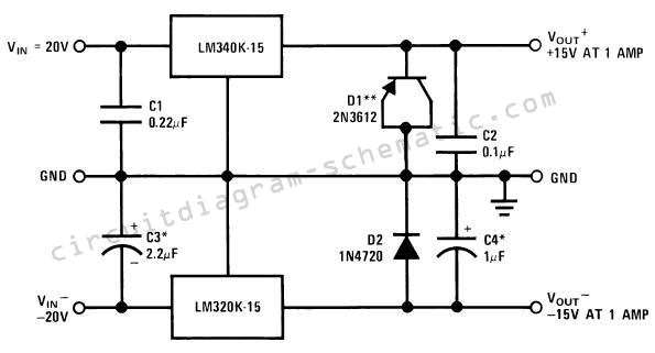
The circuit consists of a series of dual power supplies, providing a symmetrical ±15V supply for linear circuits. The same principle is applicable to non-symmetrical supplies, such as 5.0V and -12V regulators, which are used in applications like registers....
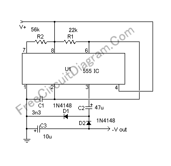
If a negative supply is required for an operational amplifier or if a negative bias voltage is needed while operating from a single supply voltage, such as in battery applications. To generate a negative supply voltage from a single positive...
The Kill A Watt is a product that measures volts, amps, and power factor of individual appliances, allowing users to calculate power consumption and running costs. However, a desire for a solution that provides similar data for an entire...
This circuit is designed to charge sealed lead-acid batteries using a solar panel in small and portable applications. A standard diode, which typically prevents the battery from discharging back through the solar panel, has been replaced with a FET-comparator...
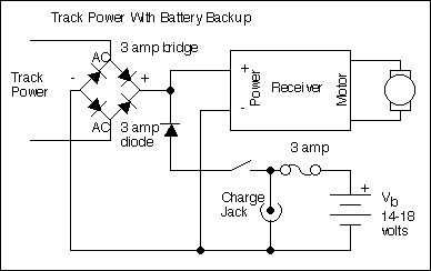
The primary motivation for utilizing battery power for trains is to eliminate the need for track cleaning and wiring. Track maintenance can pose significant challenges. Incorporating radio control into a battery-powered system enhances command control, an advantageous feature. In...
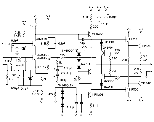
This simple audio power amplifier was originally designed for a circuit board workshop conducted by the OSU IEEE Student Group. At the workshop, 20 participants each constructed this amplifier by etching and drilling the single-sided circuit board, soldering all...