
power How can I switch a high current with a low-rated switch

To create a reliable breadboard power supply capable of switching between 5V and 12V outputs from an ATX-like SMPS, a practical approach is necessary given the limitations of available components. The circuit can be designed to utilize a combination of a switch and a diode arrangement to effectively manage the voltage outputs.
A suitable configuration would involve using a high-current DPDT (Double Pole Double Throw) switch rated for at least 2A, if available locally, to toggle between the two voltage outputs. If a 2A-rated switch cannot be sourced economically, a more viable alternative includes using a relay or a MOSFET for switching. The relay approach allows for isolation between the control signal and the power supply, ensuring that the low-rated switch can control the relay, which handles the higher current.
For the 5V output, a Schottky diode can be employed to prevent reverse current when the 12V output is selected. Schottky diodes are preferred due to their low forward voltage drop, which minimizes power loss. The diode should be rated for at least 2A to handle the maximum load without overheating.
For the 12V output, it is crucial to ensure that the components, particularly the switching element (whether a relay or MOSFET), can handle the full current of 2A. If a MOSFET is used, a logic-level N-channel MOSFET can be directly driven from the lower voltage side, providing efficient switching with minimal voltage drop.
The circuit schematic should clearly depict the connections from the ATX power supply to the Molex connector, including the switch arrangement for toggling between the 5V and 12V outputs. It is essential to include proper decoupling capacitors near the output terminals to stabilize the voltage and reduce noise. Furthermore, a fuse rated slightly above the expected load current should be incorporated to protect the circuit from overcurrent conditions.
In summary, this power supply design aims to provide a versatile and efficient solution for breadboard applications while navigating the constraints of component availability and cost.Designing and building a breadboard power supply for myself, which draws power from an ATX-like SMPS (Mains in, single Molex plug out) via a 4-pin Molex connector. The design includes a switch to select either 12V or 5V output, but the only appropriate switch I can source is rated for a paltry 30mA!
Obviously I can`t switch up to 2A with a 30mA-rated switch, but what can I do (that`s cheaper than the ~$5-10 local vendors want for 2A-rated switches) I thought of using an NPN transistor (see diagram, below), but in simulations that resulted in an unwanted voltage drop, and having the load connected to both emitters seemed to do weird things to the voltage. I realise the obvious answer here is "use a 2A-rated switch", DigiKey have plenty. The trouble is, DigiKey have considerably high shipping charges; I really have to make do with what`s available where I live.
Calrion Mar 5 `13 at 9:00 Gah! How did I not see this question when I searched Still, this seems slightly different in that I`m wanting to switch between two (different voltage) supplies. Calrion Mar 5 `13 at 9:05 You are selecting between 5V and 12V. For the 5V a simple diode will do, because it will block when you apply the 12V. For the 12V (and for the diode) you will have to use something that is rated for the current you want to draw, no alternative for that!
Wouter van Ooijen Mar 5 `13 at 11:46 No matter what voltage you supply (which transistor conducts), the current source will only take 2A. The rest of the voltage will be dissipated by the transistor. Did you really mean to draw a current source there jippie Mar 5 `13 at 18:38 🔗 External reference
Related Circuits
With the advancement of technology and the widespread use of large high-accuracy dynamic range D/A converters for full-speed digital signal processing, the generated frequency remains relatively fixed due to the phase control achieved through digital means and adjustable synthesis...
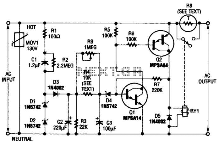
Q1 is an NPN Darlington transistor, and Q2 is a PNP Darlington transistor. MOV1 is a metal-oxide varistor, while R8 is a thermistor used for limiting inrush current. This circuit is designed to limit AC line current to a...
The circuit was designed to increase an input signal of 4 Watts to 6 Watts, operating within the VHF radio frequency band, specifically for FM transmission. This circuit is engineered to amplify radio frequency signals in the VHF band, which...
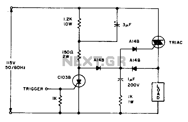
The triac will be activated at the beginning of the positive half cycle due to the current flowing through the 3 µF capacitor, provided that the C103 SCR is in the off state. The load voltage subsequently charges the...
In this modern era, any relationship characterized as master/slave may raise ethical concerns; however, for this circuit, it effectively illustrates its operation. The circuit detects the mains current supplied to a master device and controls the on/off state of...
A filter removes the DC component of the rectified AC, which is then scaled to RMS. The output is linear from 40 Hz to 10 kHz or higher. The described circuit primarily consists of a filter designed to eliminate the...