
0-30 VDC Stabilized power supply with current control 0.002-3 A
The described power supply circuit features a robust design that allows for a variable output voltage ranging from 0V to 30V DC, achieved through the use of a voltage regulator, typically based on integrated circuits such as the LM317 or similar adjustable linear voltage regulators. The output voltage can be fine-tuned using a potentiometer, enabling precise voltage settings suitable for various applications.
Incorporated within the circuit is an electronic output current limiter, which is essential for protecting sensitive components during testing. This circuit utilizes a current sensing resistor and an operational amplifier to monitor the output current. When the output current exceeds the predefined limit, the circuit automatically adjusts the output voltage, thereby preventing excessive current flow. The current limit can be set to a minimum of 2 mA, allowing for testing of low-power devices, up to a maximum of 3 A, accommodating a wide range of experimental setups.
The power supply circuit is typically powered by an AC source, which is rectified and filtered to provide a stable DC input for the voltage regulator. Additional filtering capacitors are included to smooth out any ripple in the output voltage, ensuring a clean and stable power supply.
Safety features may also be integrated, such as thermal shutdown and short-circuit protection, to further safeguard both the power supply and the devices being powered. The entire assembly is usually housed in a durable enclosure with adequate ventilation to dissipate heat generated during operation.
Overall, this power supply design is an invaluable tool for electronic experimentation, providing flexibility in voltage and current settings while ensuring safety and reliability in laboratory environments.This is a high quality power supply with a continuously variable stabilised output adjustable at any value between 0 and 30VDC. The circuit also incorporates an electronic output current limiter that effectively controls the output current from a few milliamperes (2 mA) to the maximum output of three amperes that the circuit can deliver.
This feature makes this power supply indispensable in the experimenters laboratory as it is possible to limit the current to the typical maximum that a circuit under test may require, and power it up then, without any fear that it may be damaged if something goes wrong. 🔗 External reference
Related Circuits
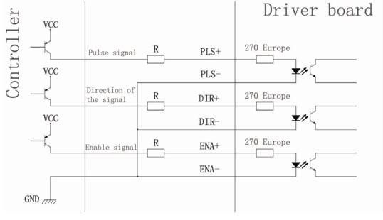
Connection of a drive and a two-phase hybrid stepper motor using a four-wire system, with the motor windings configured in both parallel and series connections. This method allows for high-speed performance, although it requires a large drive current (1.73...
Tone Control. Parts: Total Quantity of Parts: Substitutions C1, C3, C5, C7, C15, C16 - 6 pieces of 2.2µF Electrolytic Capacitors; C2, C6 - 2 pieces of 0.05µF Ceramic Capacitors. The tone control circuit is designed to adjust the frequency...
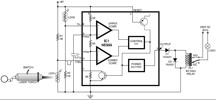
This circuit is designed around a 555 timer and utilizes a minimal number of components. Its simplicity allows even beginners to easily assemble and operate it as a control device. A readily available laser pointer can be used to...
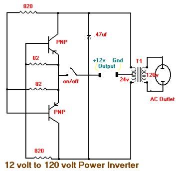
This is the schematic diagram of a 15W inverter circuit. The circuit is based on a PNP power transistor such as the TIP32 and other similar transistors. This inverter produces a square wave output, which may cause some noticeable...
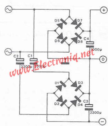
If a double power supply is desired but a center-tapped transformer is unavailable, an electronic circuit can be utilized in the following configuration. This circuit employs a second rectifier bridge connected to the secondary coil of the transformer, utilizing...
The following circuit illustrates the use of the AD8531 integrated circuit for the automatic control of LCD panel backlighting. Features include the ability to compensate for aging effects. The AD8531 is a precision operational amplifier that is well-suited for applications...