
Tone Control
The tone control circuit is designed to adjust the frequency response of an audio signal, allowing for enhancement or attenuation of specific frequency ranges. This circuit typically employs a combination of capacitors and resistors to create filters that modify the audio signal's bass, midrange, and treble characteristics.
In this particular tone control circuit, there are two types of capacitors utilized: six 2.2µF electrolytic capacitors and two 0.05µF ceramic capacitors. The electrolytic capacitors (C1, C3, C5, C7, C15, C16) are primarily used for coupling and decoupling applications, where they help to block DC voltage while allowing AC signals to pass. Their larger capacitance value is suitable for low-frequency applications, making them ideal for bass enhancement in the tone control circuit.
The ceramic capacitors (C2, C6), with a smaller capacitance value of 0.05µF, are typically used for high-frequency filtering. These capacitors are known for their stability and reliability, making them suitable for treble adjustments. The combination of these capacitors allows the tone control circuit to effectively shape the audio signal across a wide frequency range.
The overall design of the tone control circuit may incorporate potentiometers or variable resistors, which enable users to adjust the level of bass, midrange, and treble. By manipulating these controls, the user can achieve the desired tonal balance for various audio sources, enhancing the listening experience.
In summary, the tone control circuit described is an essential component in audio systems, providing flexibility in sound customization through the strategic use of electrolytic and ceramic capacitors.Tone Control. Parts: Part Total Qty. Substitutions C1, C3, C5, C7, C15, C16 6 2.2uf Electrolytic Capacitor C2, C6 2 0.05uF Ceramic. 🔗 External reference
Related Circuits
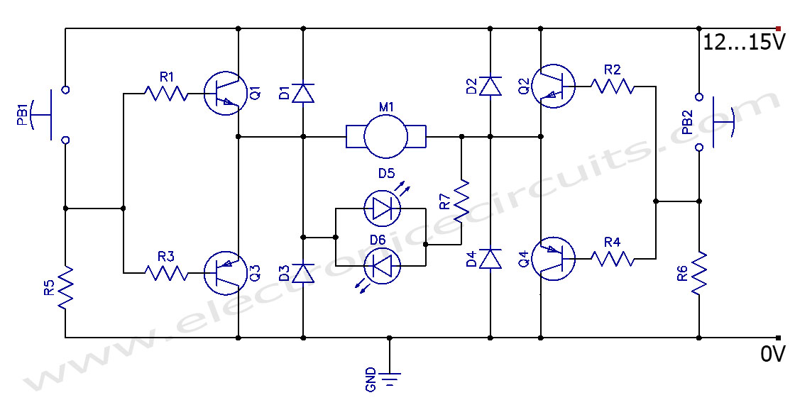
This circuit can control the direction of a DC motor, allowing it to operate in both clockwise and counterclockwise directions (forward and backward). The described circuit employs an H-bridge configuration, which is essential for reversing the polarity of the voltage...

An SMS-based home appliance control system is being developed using the ATtiny2313 microcontroller. There are issues with programming the microcontroller. The SMS-based home appliance control system utilizes the ATtiny2313 microcontroller, which is a versatile 8-bit microcontroller from the AVR family....
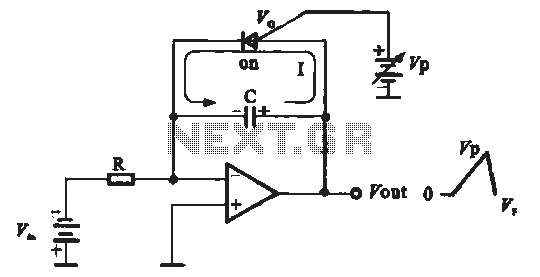
A sawtooth voltage-controlled oscillator operates by first generating a negative potential maximum at the output of the comparator. This output is then fed to the inverting input terminal through resistor R1, which is part of the relaxation oscillator. The...
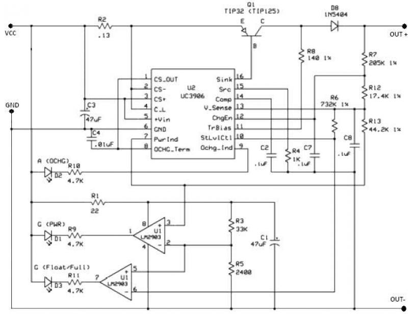
The UC3906 battery charger circuit controller includes all necessary circuitry to manage the charge and hold cycles for sealed lead-acid batteries. This circuit is specifically designed to deliver the appropriate charging voltage and current based on the battery's temperature...

The circuit is constructed using two 555 timer integrated circuits (ICs), designated as U1 and U2. U1 is configured as a variable duty cycle oscillator with a fixed time period of approximately 0.1 seconds. The duty cycle can be...
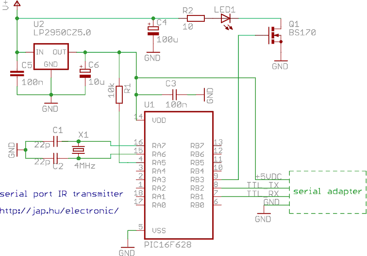
This is a programmable infrared (remote control) transmitter, which can be controlled from a PC serial port. It is capable of sending many remote control formats, including the Philips RC-5 standard. Exact formats with the timing parameter names are...
Warning: include(partials/cookie-banner.php): Failed to open stream: Permission denied in /var/www/html/nextgr/view-circuit.php on line 713
Warning: include(): Failed opening 'partials/cookie-banner.php' for inclusion (include_path='.:/usr/share/php') in /var/www/html/nextgr/view-circuit.php on line 713