
laser controlled on off switch
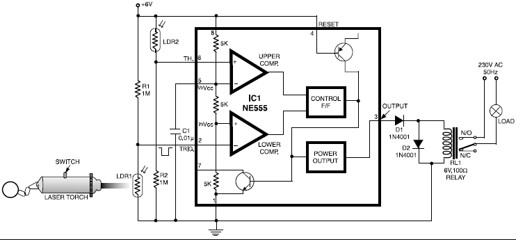
The circuit primarily consists of a 555 timer configured in a monostable or astable mode, depending on the desired application. The LDRs serve as light sensors that detect the laser beam's presence. When the laser beam strikes LDR1, it reduces the resistance of the sensor, triggering the 555 timer to activate the relay. This relay acts as a switch, allowing a higher power device, such as a fan or audio system, to be turned on. Conversely, when the laser beam is directed at LDR2, it similarly activates the 555 timer but in a manner that resets the relay, thus turning off the connected device.
To ensure optimal performance, the circuit should be housed in a protective enclosure to prevent interference from ambient light, as the effectiveness of the LDRs diminishes in well-lit conditions. The choice of components, including the relay specifications and the values of resistors and capacitors in the 555 timer circuit, should be tailored to the specific load requirements of the devices being controlled. Power supply considerations are also essential; the circuit may be powered by a standard battery or a DC power supply, depending on the application.
In summary, this circuit offers a practical solution for remote control of various electrical devices, with significant versatility and ease of use, making it suitable for a wide range of applications in home automation and other electronic control systems.This circuit is built around a 555timer using very few components. Since the circuit is verysimple, even a novice can easily build itand use it as a controlling device. A laser pointer, now easily available in the market, can be used to operate this device. This circuit has been tested in operationalconditions from a distance of500 metres and was fou nd to work satisfactorily though it can be controlledfrom still longer distances. Aiming(aligning) the laser beam exactly on tothe LDR is a practical problem. The circuit is very useful in switchingon/off a fan at night without gettingoff the bed. It can also be used forcontrolling a variety of other deviceslike radio or music system. The limitationis that the circuit is operational only in dark or dull-lit environments. By focussing the laser beam onLDR1 the connected gadget can be activatedthrough the relay, whereas by focussinglaser beam on LDR2 we canswitch off the gadget. 🔗 External reference
Related Circuits
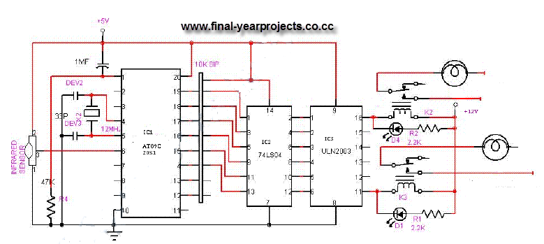
This is a comprehensive electrical project report on an Infrared Remote Control On/Off Switch, submitted to fulfill the requirements for the Bachelor of Engineering degree in Electrical Engineering. The project is designed to control the operation of home appliances...
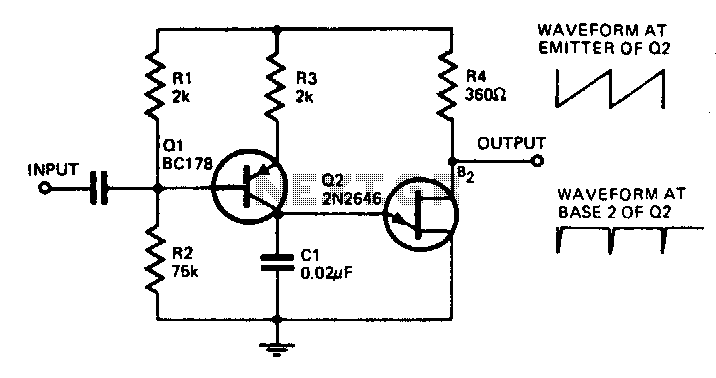
With the component values shown, the oscillator has a frequency of 8 kHz. When an input signal is applied to the base of Q1, the current flowing through Q1 is varied, thus affecting the time required to charge C1....
Operating high-beam headlights while driving on highways can significantly enhance visibility; however, it poses a blinding risk to other drivers. This straightforward circuit can be integrated into the headlight switch to facilitate automatic switching between high and low beam...
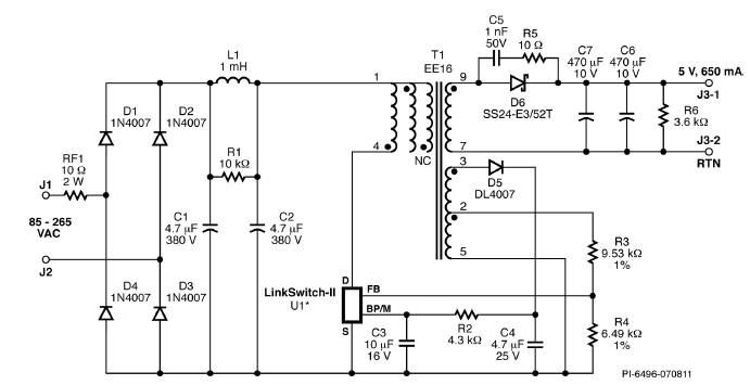
A simple 3.25W constant voltage/constant current (CV/CC) charger can be designed using the LinKSwitch family IC manufactured by Power Integrations. This electronic circuit project is intended to provide a 5-volt output with a maximum current of 650mA. The 3.25W...
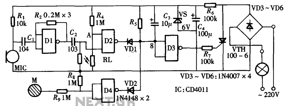
The circuit integrates sound and light control with touch functionality, creating a fully operational delay section light switch circuit. It consists of light control, voice circuits, and a touch control circuit, all triggered by a thyristor switch. The described circuit...
This circuit illustrates the TDA1054 tone control stereo preamplifier circuit diagram. Features include the National Semiconductor LM35 integrated circuit, which utilizes semiconductor technology. The TDA1054 is a versatile integrated circuit designed for use in audio applications, particularly in tone control...
Warning: include(partials/cookie-banner.php): Failed to open stream: Permission denied in /var/www/html/nextgr/view-circuit.php on line 713
Warning: include(): Failed opening 'partials/cookie-banner.php' for inclusion (include_path='.:/usr/share/php') in /var/www/html/nextgr/view-circuit.php on line 713