
0-360 phase shifter circuit diagram

The J202 JFET (Junction Field Effect Transistor) is utilized in this circuit to achieve precise phase shifting capabilities, making it suitable for applications in audio processing, signal modulation, and other electronic systems requiring phase manipulation. The inclusion of a 1 megohm potentiometer enables users to adjust the phase shift dynamically, providing a range of 0 to 180 degrees. This flexibility is crucial for tuning the circuit to achieve desired signal characteristics.
In the circuit design, each JFET stage is connected in a manner that allows the output of one stage to serve as the input for the next, thereby cascading the phase shift effect. The high input impedance of the J202 JFET ensures minimal loading on the preceding phase shift network, preserving signal integrity and preventing distortion. This characteristic is particularly advantageous in sensitive applications where signal fidelity is paramount.
The potentiometer is connected to the gate of the JFET, allowing for variable control over the gate voltage, which in turn influences the channel conductivity and the resultant phase shift. The circuit may also incorporate bypass capacitors to stabilize the power supply and reduce noise, ensuring reliable operation.
Overall, the design leverages the unique properties of JFETs and the adjustable nature of the potentiometer to create a versatile phase shifting circuit suitable for a variety of electronic applications.Each J202 JFET stage provides up to 180 phase shift by 1 megohm potentiometer control. Potentiometer complete control groups. JFETs are ideal for the designated circuit, becaus e they do not load phase shift network.
Related Circuits
This Wien bridge oscillator is straightforward and, like all Wien oscillators, exhibits low distortion. The resonance frequency can be easily adjusted. The Wien bridge oscillator is a type of electronic oscillator that generates sine waves. It is based on the principle...
Build the LC oscillator shown at the bottom of this page for a school project, but there are some challenges in translating the theoretical circuit into a real-world application. The understanding of the circuit's operation on paper is clear....
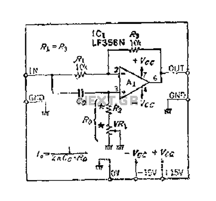
An accurate phase shift of 90 degrees can be achieved using a variable resistor (VR) and an operational amplifier (op-amp). The adjustment allows for a specific frequency to be manipulated. The phase shift can range from 180 degrees to...
The Motorola company's MC14440 CMOS integrated circuit is designed for timing and displaying calendar functions. It utilizes a 32.768 kHz NT cutting type quartz crystal along with fine-tune capacitance to generate time-based signals. The display circuit operates on a...

A pH electrode measures hydrogen ion (H+) activity and generates an electrical potential or voltage. The operation of the pH electrode is based on the principle that an electric potential develops when two liquids of different pH come into...

A South African company has developed a 5-kilowatt Fuel Free Generator and discovered that the longevity of the batteries is significantly affected by the process. There are various types of batteries available for testing, including different lead-acid batteries, gel...