
1.5 Volt LED Flasher Circuits

The described LED flasher circuits utilize low-voltage power sources and simple components to create effective flashing light displays. The first circuit employing the LM3909 IC is a classic design known for its efficiency and ease of use. This integrated circuit is specifically designed for LED flashing applications, allowing for precise control over the flashing rate with minimal external components. The timing capacitor, when charged, determines the duration of the ON and OFF states of the LED, thus controlling the flash rate.
In contrast, the second circuit, designed by Andre De-Guerin, takes a more intricate approach by utilizing a 100uF capacitor to effectively double the voltage supplied by a single 1.5V battery. This configuration allows for a higher operating voltage of approximately 3 volts, which is beneficial for driving standard LEDs that require higher forward voltages. The use of two sections of a 74HC04 hex inverter as a square wave oscillator is a notable feature of this design. The oscillator generates a square wave signal that dictates the flashing frequency of the LED.
The third section of the hex inverter acts as a buffer, which is essential for charging the timing capacitor through a 470-ohm resistor. When the buffer output is at +1.5 volts, it facilitates the charging of the capacitor. Once the buffer output transitions to ground, the stored charge in the capacitor is released, creating a potential difference sufficient to forward-bias the LED, thus illuminating it. The design ensures that the LED operates at a current of approximately 3 mA, making it suitable for high-brightness LEDs that can efficiently convert electrical energy into light.
Overall, these circuits exemplify a blend of simplicity and functionality, offering effective solutions for LED flashing applications with minimal power requirements.The LED flasher circuits below operate on a single 1.5 volt battery. The circuit on the upper right uses the popular LM3909 LED flasher IC and requires only a timing capacitor and LED. The top left circuit, designed by Andre De-Guerin illustrates using a 100uF capacitor to double the battery voltage to obtain 3 volts for the LED.
Two sections of a 74HC04 hex inverter are used as a squarewave oscillator that establishes the flash rate while a third section is used as a buffer that charges the capacitor in series with a 470 ohm resistor while the buffer output is at +1.5 volts. When the buffer output switches to ground (zero volts) the charged capacitor is placed in series with the LED and the battery which supplies enough voltage to illuminate the LED.
The LED current is approximately 3 mA, so a high brightness LED is recommended. 🔗 External reference
Related Circuits
This circuit can be utilized by individuals, such as a gentleman summoning his butler, a manager calling for his secretary, or, as in the author's case, to call children down for dinner without raising one's voice over the noise...
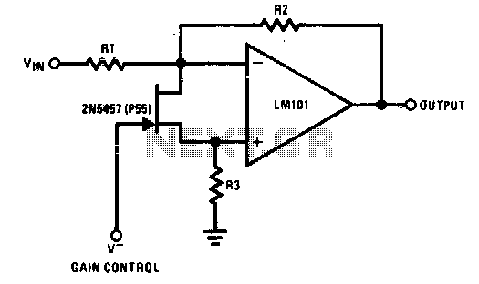
The 2N5457 functions as a voltage-variable resistor with a maximum RdS of 800 ohms. Given that the differential voltage on the LM101 is in the low millivolt range, the 2N5457 JFET exhibits linear resistance over several decades, offering excellent...
This amplifier circuit exhibits a very low power consumption, with a total current draw of 675 nA. The output voltage swing is 300 mV peak-to-peak (pp) with a gain of 20. The amplifier circuit is designed to operate with minimal...
This simple counter can be used to count pulses, serving as the basis for a customer counter, similar to those found at the entrances of some stores, or for any other application requiring counting. The described simple counter circuit is...
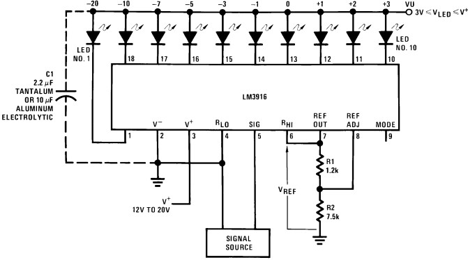
Convert the LEDs into LED bar graphs that display intensity. For instance, a song with a strong bass should cause the bar graph to rise to the maximum. The segments of the LED bar graph should consist of individual...
Five pins RA0 to RA4 are used as inputs. The pins are connected to the 5V average resistance 10K (Pull-up). So when no switch is not depressed all the pins have a high potential (HI +5 V). When one...