
call acknowledged schematics

This circuit design effectively addresses the need for a simple yet efficient communication method in environments with background noise. The use of a two-transistor multivibrator allows for the generation of a pulsed signal that not only activates the buzzer but also provides visual feedback through the red LED. This dual indication system enhances usability, especially in scenarios where auditory signals may go unnoticed.
The selection of components is critical for optimal performance. The two transistors should be chosen based on their switching speed and gain characteristics to ensure reliable operation of the multivibrator. The capacitors used in the timing circuit should have values that allow for the desired frequency of approximately 1.5 Hz, which can be fine-tuned based on the specific application requirements. The diode D1 plays an essential role in maintaining the integrity of the multivibrator's operation by preventing feedback from the buzzer, ensuring that the pulsing action remains consistent regardless of the load changes caused by the buzzer.
The circuit’s power requirements are minimal, making it suitable for battery operation, which adds to its convenience and portability. The choice of a 9-V battery strikes a balance between sufficient voltage to drive the components and ease of availability. The design also allows for flexibility in LED selection, accommodating various types and colors, thus enabling customization based on user preference or availability of components.
In summary, this circuit serves as an effective solution for remote signaling in noisy environments, combining auditory and visual alerts to ensure that messages are successfully communicated and acknowledged. Its simple design, low power requirements, and adaptability make it a practical choice for numerous applications.This circuit could be used (depending on your circumstances) by a gentleman to summon his butler, a manager his secretary or as in the author`s case to call the kids down to dinner without having to shout above the level of the CD player/TV/games console in their bedroom. Rather than resorting to a full-blown intercom system, a simpler solution wa s envisaged and while a buzzer could easily fulfil this function, this circuit has the advantage of providing a visual indication of a call as well as confirming to the caller that the message` has been received. This is especially useful in the latter case, as the call may be easily drowned out by the music playing in the headphones.
The circuit, which requires no complicated switching, uses a simple two-wire connection between the two stations and utilises the fact that the forward voltage drop of a blue (or white) LED is greater than that of a red, green or yellow one. The circuit is based on a two-transistor multivibrator which is used to pulse a red LED (D3) as well as the buzzer Bz1 on and off at about 1.
5 Hz when push button S1 is closed. This frequency may of course be altered if required by changing the values of the capacitors. The diode D1 in series with the collector of transistor T2 is required to isolate the output from the effects of the buzzer circuitry, which would alter the multivibrator frequency. In principle, the multivibrator could be dispensed with but a pulsed buzzer/flashing led is much more noticeable than a continuous signal especially in noisy conditions.
Since the voltage across a red LED is typically about 1. 5 V while a blue LED requires at least 2. 5 V to 3 V to light, the blue LED will remain off when the call button S1 is pressed. Despite being rated for operation at 3-12 V, most piezo sounders can still produce a piercing sound from the pulsed 1. 5-V available across the red LED which should get the attention of even the most preoccupied teenager.
When the recipient presses the acknowledge (push to break) switch S2, the red LED/buzzer are disconnected allowing the blue LED to flash at the sending station indicating to the caller that his call has been received. Alternatively, if a blue LED is not available, a red or green type in series with a forward biased silicon diode to raise its forward voltage above that of the red LED in the receiver could be used instead.
The circuit may be powered by a 9-V battery, a mains power supply being unnecessary in view of the low power consumption and infrequency of use of the circuit. 🔗 External reference
Related Circuits
The circuit consists of two main components: (1) a power supply circuit featuring a transformer (T) that steps down AC 220V to 33V, followed by a full-wave rectifier, a filter, and a three-terminal regulator that outputs +24V. This circuit...

The circuit is designed to operate with an external power supply, which is why it does not include a transformer, rectifier, or filter capacitors in the schematic. However, these components can be added if desired. To utilize the circuit,...

IC1 operates as an oscillator that drives an infrared LED with pulses of 0.8 milliseconds at a frequency of 120 Hz, generating approximately 300 mA of peak current. Diodes D1 and D2 are aligned and positioned a few centimeters...
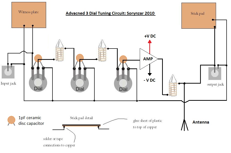
An advanced radionics schematic designed to enhance the power output of a tuning circuit. This schematic outlines a sophisticated approach to improving the efficiency and output power of a tuning circuit used in radionics applications. The circuit typically includes a...

To quickly determine if a remote control transmitter is functioning properly, a remote control detector can be utilized. If the remote control transmitter is operational, the detector will emit an audible alarm signal. This detector is capable of assessing...
Q1 and Q2 create an ALL-ON ALL-OFF circuit that, when in the off state, draws negligible current. P1 initiates the circuit, activating the relay and powering the two integrated circuits (ICs). The lamp is energized through the relay switch,...