
1.5 volt LED flasher schematic
The described LED flasher circuit utilizes a 74HC14 hex inverter, a component known for its low power consumption and high efficiency, making it suitable for battery-operated devices. The circuit operates at a nominal voltage of 1.5 volts, powered by a single 'D' cell battery. The design incorporates a square wave oscillator configuration using pins 1 and 2 of the 74HC14, generating a periodic square wave signal that serves as the timing mechanism for the LED flashing.
The alternate flashing of the two LEDs is achieved through additional sections of the hex inverter, which are configured to produce short pulses of approximately 10 milliseconds in duration. This is done by wiring the output of the oscillator to trigger the other inverter sections, allowing the LEDs to flash in a complementary manner. The use of a capacitor charge pump in the output stages is critical, as it boosts the output voltage to provide sufficient current to drive the LEDs effectively. This charge pump mechanism ensures that the LEDs receive the necessary voltage for optimal brightness, even as the battery voltage declines over time.
Current consumption is a crucial aspect of this circuit, with an average draw of 800 microamperes from the 'D' cell. The peak current for the LEDs is approximately 40 milliamperes when the battery is fresh, tapering down to about 10 milliamperes as the battery voltage approaches the cutoff of 1.1 volts. Given the capacity of an alkaline 'D' cell, estimated at 12 amp hours, the theoretical operational lifespan of the circuit is calculated to be around 15,000 hours or roughly 625 days, assuming optimal conditions and no additional load on the battery.
In summary, this LED flasher circuit is designed for longevity and efficiency, effectively utilizing a hex inverter to create a simple yet effective LED flashing mechanism while maintaining low power consumption suitable for extended battery life.This 1.5 volt led fasher runs more than a year on a single 'd" cell and alternately flashes 2 LEDs at about a 1 second rate. The circuit employs a 74HC14 CMOS hex inverter that will operate at very low voltages (less than 1 volt).
One section is used as a squarewave oscillator (pins 1 and 2), while the others are wired to produce a short 10mS pulse on alternate edges of the square wave so the LEDs will alternate back and forth. The output sections each use a capacitor charge pump to increase the voltage for the LEDs. The circuit draws an average current of 800uA from the 'D' battery and the LED peak current is about 40mA with a fresh battery and drops to about 10mA as the battery voltage falls to 1.1 volts. The capacity of a alkaline 'D' cell is about 12 amp hours with a cutoff voltage of 1.1 so the circuit should run about 12/.0008 = 15000 hours or maybe 625 days, but I haven't verified that yet.
🔗 External reference
Related Circuits
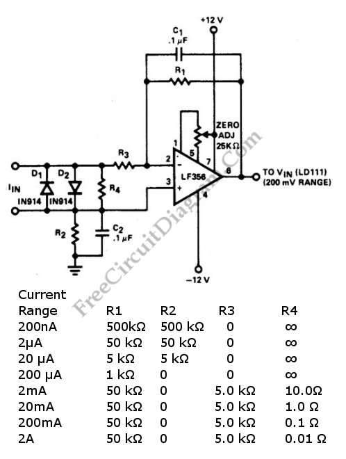
A current-to-voltage converter circuit can be constructed using a single resistor. This design is straightforward, as any current flowing through a resistor will naturally generate a voltage. A current-to-voltage converter, also known as a transimpedance amplifier, is primarily utilized to...
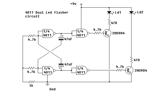
This simple circuit utilizes NAND gates to alternately flash two LEDs. The two 47µF capacitors set the flashing frequency. It is advisable to include a decoupling capacitor across the power supply. The circuit was constructed using the specified components...
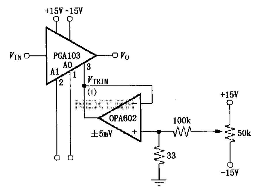
The PGA103 offset voltage correction circuit is designed to minimize the offset voltage for the PGA103 laser correction, ensuring that the gain for three typical offset voltage levels (relative to input) remains below 200 V. Each gain is associated...
The bi-directional sequencer employs a 4-bit binary up/down counter (CD4516) along with two "1 of 8 line decoders" (74HC138 or 74HCT138) to create the well-known "Night Rider" display. A Schmitt Trigger oscillator generates the clock signal for the counter,...
While I would have liked a 4 channel chip with about 20 Watt per channel, the local parts store didn't have any yet, so I opted for two TA8215AH stereo chips, selected by their low price in this particular...
Almost all 24V power systems in trucks, 4WDs, RVs, boats, etc., utilize two series-connected 12V lead-acid batteries. The charging system can only sustain the total voltage of the individual batteries. If one battery is failing, this circuit will illuminate...