
4011 dual led flasher
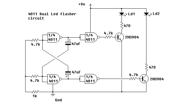
The circuit design employs a 4011 Quad NAND gate integrated circuit, which contains four independent NAND gates. The configuration is designed to create a bistable multivibrator or flip-flop arrangement that alternates the state of two LEDs, resulting in a blinking effect. The two 47µF capacitors are pivotal in determining the timing characteristics of the circuit. These capacitors, in conjunction with the resistors (not specified in the description but typically included in such circuits), establish the charge and discharge cycles that control the frequency of the LED flashing.
A decoupling capacitor should be placed across the power supply terminals of the 4011 IC to filter out any noise and stabilize the voltage supply, ensuring reliable operation of the circuit. This capacitor typically has a value of 0.1µF and is placed as close as possible to the power pins of the IC.
To construct the circuit, each NAND gate is configured to create a feedback loop, where the output of one gate is connected to the input of another. This arrangement allows for the alternation of the output states, causing one LED to turn on while the other turns off, and vice versa. The timing of the LED flashes can be adjusted by varying the capacitance of the 47µF capacitors or by changing the associated resistors in the circuit.
In summary, the circuit effectively demonstrates the use of NAND gates for creating an alternating LED flash effect, highlighting the fundamental principles of digital electronics and timing circuits. Proper component selection and configuration are crucial for achieving the desired operational characteristics.This simple circuit uses NAND Gates to alternately flash two led`s. The two 47uF capacitors determine the flash frequency. It is a good idea to use a decoupling capacitor across the power supply. I made this circuit using the components shown and it worked fine. The IC that I used is the 4011 Quad 🔗 External reference
Related Circuits
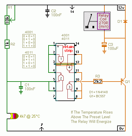
A CMOS 4001 or a CMOS 4011 can be utilized in this circuit, as both contain four two-input gates. The inputs of each gate are connected together, allowing them to function as simple inverters. This means that when both...
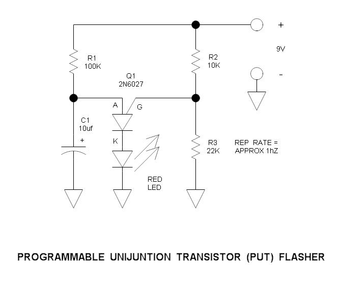
This is a simple circuit that illustrates the function of the programmable unijunction transistor. It can be quickly wired on a proto-board. The circuit utilizes a programmable unijunction transistor (PUT) to demonstrate its operation as an oscillator. The PUT, which...

The objective is to vary two voltages, V1 and V2, by an equal percentage of their respective ranges (V1MAX - V1MIN and V2MAX - V2MIN), where V1MAX, V1MIN, V2MAX, and V2MIN are independent of one another. A common approach...
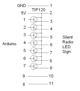
The project addresses a brightness issue with the LED display. The original design using a 4017 counter was ineffective because it lacked the capability to turn off the display while updating the shift registers. Consequently, the decision was made...
Telephone ringer utilizing 556 dual timers. This circuit generates ringing tones resembling those of a telephone by employing modulated rectangular waves of varying time periods. The telephone ringer circuit employs two 556 dual timer ICs configured to generate modulated rectangular...
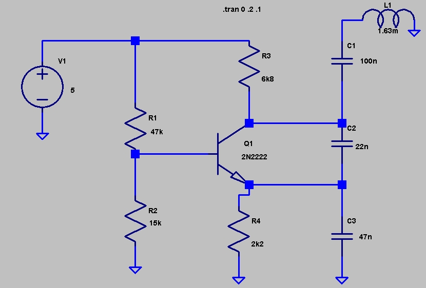
This circuit was featured in the "design ideas" section of EDN's March 5, 2007 issue. It is a relatively simple circuit that allows investigation into how the inductance of a toroid (or any core) is affected by saturation, which...