
Battery Equality Monitor Circuit Schematic
The described circuit functions as a voltage monitoring system for dual 12V lead-acid batteries configured in series to create a 24V power supply. This configuration is prevalent in various applications, including trucks, 4WD vehicles, recreational vehicles (RVs), and marine vessels. The primary goal of the circuit is to provide early detection of battery health issues by monitoring the voltage levels of each battery.
The circuit utilizes a microcontroller or a simple comparator circuit to measure the voltage across each battery. By comparing the voltages, the circuit can determine if one of the batteries is underperforming or failing. When a significant voltage difference is detected, indicating that one battery is not holding its charge as well as the other, an LED indicator is activated. This visual alert serves as a warning to the user, allowing for timely intervention before complete battery failure occurs.
In terms of design, the circuit should include necessary components such as resistors to limit current to the LED, a voltage divider to scale down the battery voltages to a manageable level for the comparator or microcontroller, and possibly a relay if further actions are required, such as disconnecting the failing battery from the circuit. Additionally, the idle current consumption of the circuit must be minimized, allowing it to remain connected across the batteries without draining them excessively.
Overall, this monitoring circuit enhances the reliability of 24V systems by providing critical feedback on battery health, thereby prolonging the lifespan of the batteries and ensuring the uninterrupted operation of connected systems.Almost all 24V power systems in trucks, 4WDs, RVs, boats, etc, employ two series-connected 12V lead-acid batteries. The charging system can only maintain the sum of the individual battery voltages. If one battery is failing, this circuit will light a LED. Hence impending battery problems can be forecast. The circuit works by detecting a voltage difference between the two series connected 12V batteries. Idle current is low enough to allow the unit to be permanently left across the batteries 🔗 External reference
Related Circuits
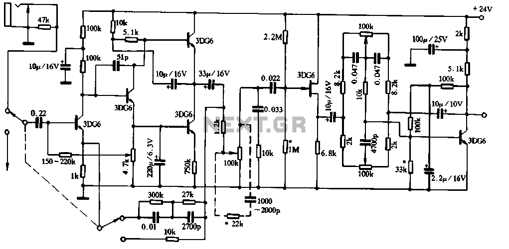
Figure 1-91 illustrates a practical loudness volume control circuit designed for integration with a preamplifier and tone control system. This circuit is positioned behind the output capacitor load (OCL) and can be connected to the main amplifier. Its effectiveness...
This remote transmits a tone using an infrared LED. This tone is decoded by the receiver. Since the receiver only switches when it "hears" the tone, there are no accidental activations. The described circuit consists of a remote control unit...
These two tank circuits appear to broaden the operating spectrum. The accompanying information sheet indicates that when both circuit stages oscillate at the same frequency, the power output reaches its maximum. This suggests that if the tunable tank circuit...
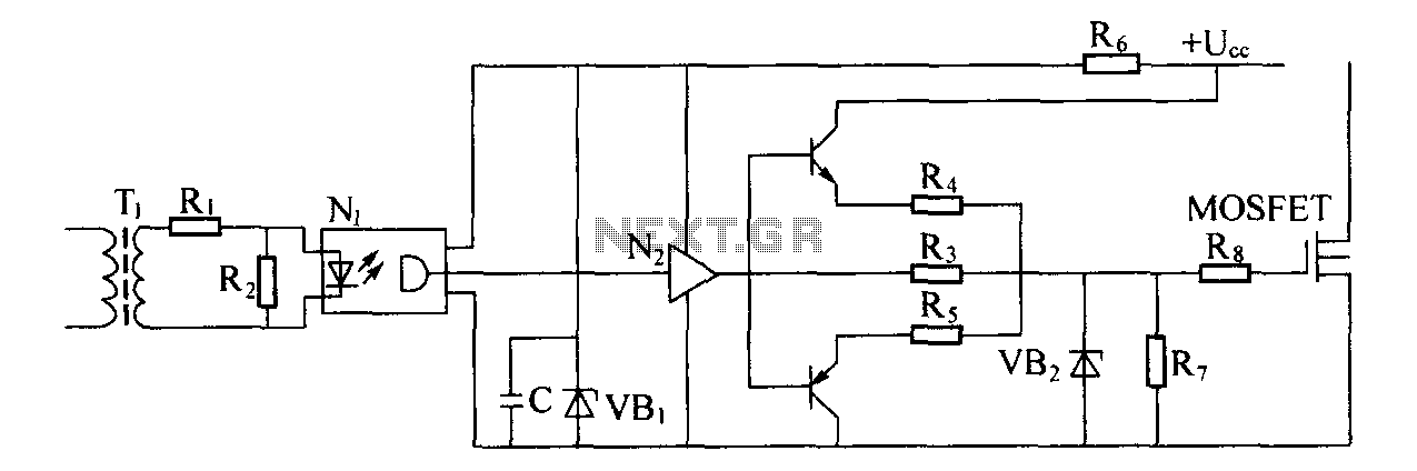
Driver circuit diagram: The primary function of the driver circuit is to serve as a variable width pulse width modulator output power amplifier, providing a drive signal to high voltage power switching devices. The driving circuit typically plays a...
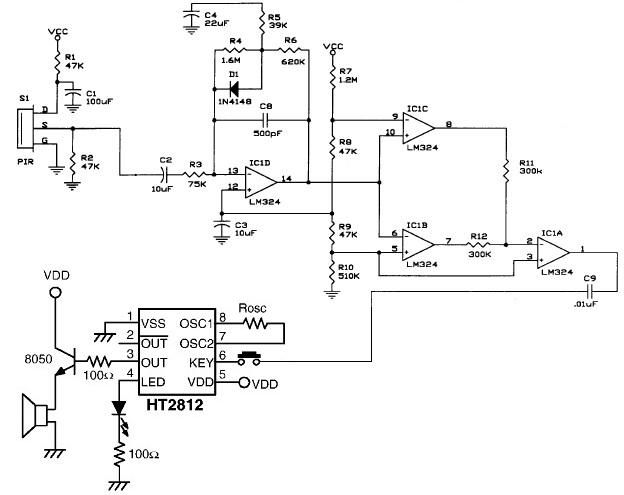
The operational amplifier IC1D modifies the frequency response to enhance the frequencies generated during motion detection while eliminating others, such as noise or gradual temperature variations. When the output voltage of IC1D exceeds 1.67V, it activates pins 8 and...
With a 1.5V battery supply, the integrated circuit LM3909 can drive the light-emitting diode NSL5027. The 300μF electrolytic capacitor acts as a timing capacitor, which limits the flash speed to approximately 1Hz. The circuit utilizes the LM3909, a popular LED...
Warning: include(partials/cookie-banner.php): Failed to open stream: Permission denied in /var/www/html/nextgr/view-circuit.php on line 713
Warning: include(): Failed opening 'partials/cookie-banner.php' for inclusion (include_path='.:/usr/share/php') in /var/www/html/nextgr/view-circuit.php on line 713