
1.5 Volt LED Flashers circuit
The LED flasher circuit using the LM3909 integrated circuit (IC) is designed for efficient operation with minimal components. This circuit is particularly notable for its simplicity and effectiveness in producing a flashing LED effect, making it suitable for various applications, including indicators, decorative lighting, and low-power signaling devices.
The LM3909 IC is a specialized LED flasher that incorporates a timing mechanism to control the flashing rate of the LED. The operation of the circuit is based on a single 1.5-volt battery, which is sufficient to power the LM3909 and the connected LED. The circuit typically consists of the LM3909 IC, a timing capacitor, and a resistor to set the flash rate. The timing capacitor charges and discharges, creating a pulse that turns the LED on and off at a predetermined frequency.
In terms of component values, the timing capacitor's capacitance and the resistor's resistance will directly influence the flashing rate of the LED. A larger capacitor will result in a slower flash rate, while a smaller capacitor will produce a faster flashing effect. Similarly, changing the resistance will adjust the timing cycle, allowing for customization of the LED's flashing behavior.
The simplicity of the circuit makes it highly accessible for hobbyists and educators, as it can be easily assembled on a breadboard or printed circuit board (PCB). Furthermore, the low power consumption of the LM3909 ensures that the circuit can operate for extended periods on a single battery, making it an excellent choice for portable applications.
Overall, the LED flasher circuit with the LM3909 IC exemplifies an efficient and effective design for creating visual signals with minimal components and power requirements.The LED flasher circuits below operate on a single 1.5 volt battery. The circuit on the upper right uses the popular LM3909 LED flasher IC and requires only a timing capacitor and LED.. 🔗 External reference
Related Circuits
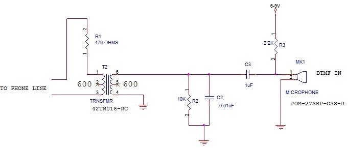
What type of microphone or mouthpiece can be used to connect to a POTS (Plain Old Telephone Service) telephone line to send DTMF (Dual-Tone Multi-Frequency) tones only, without transmitting voice? Is a standard microphone suitable, or must it be...
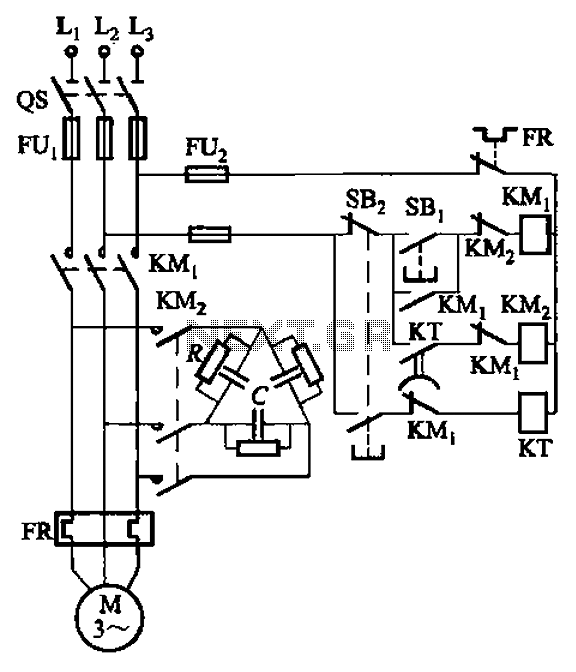
The circuit illustrated in Figure 3-151 consists of capacitor banks arranged in a specific configuration. Figure 3-151 (a) depicts capacitor banks connected in a shaped manner, which is suitable for use with shaped or Y-connected motors. Figure 3-151 (b)...
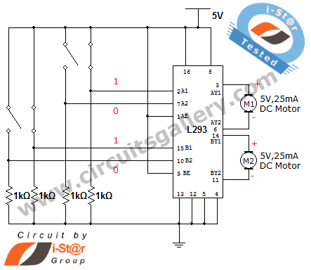
How can a DC motor be rotated in clockwise and counterclockwise directions? This is a common question posed by many robotics beginners. DC motor driver circuits are essential components in robotics workshops. The L293D IC is frequently utilized for...
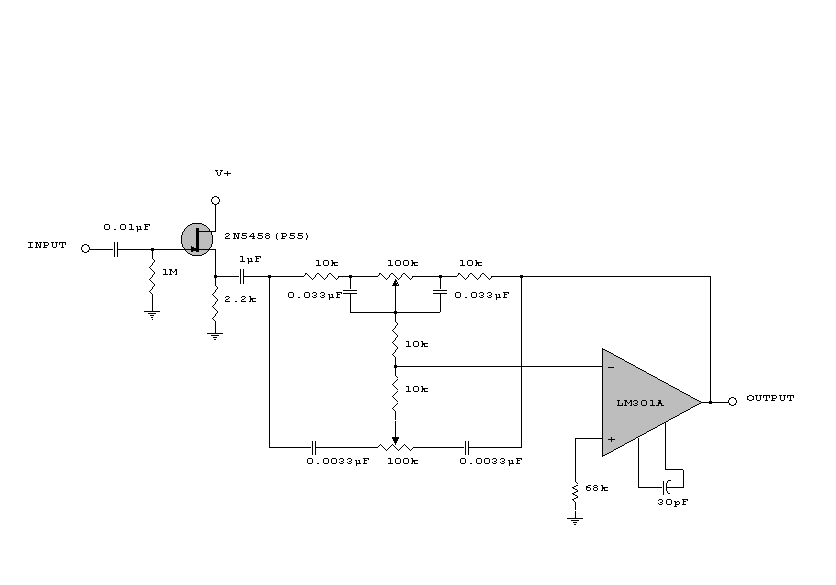
This circuit is a simple series tone control circuit. It utilizes the surgical amplifier LM301A. The JFET 2N3684 provides high input impedance and low noise for the unbuffered operational amplifier, which operates in an equalizer (EQ) configuration. Further details...
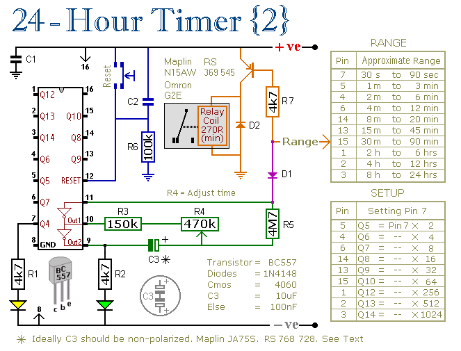
These two circuits are multi-range timers that offer periods of up to 24 hours and beyond. They can function as repeating timers or single-shot timers. Both circuits are fundamentally the same, with the primary distinction being their behavior in...
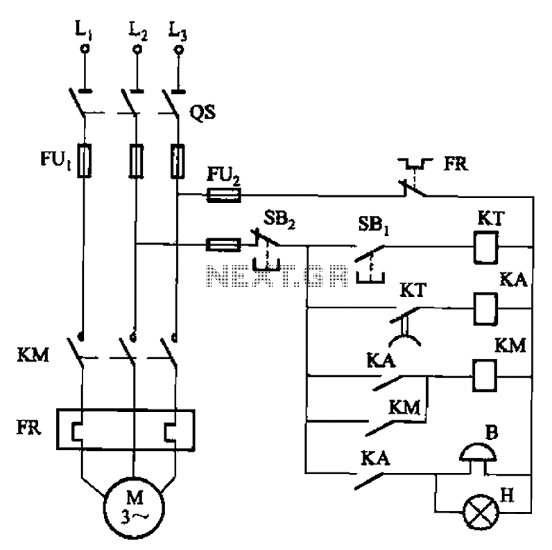
The circuit shown in Figure 3-21 is designed to produce a motor startup sound and a light signal indicating the completion of the startup process, after which the signal ceases. This circuit is tailored to control the motor for...
Warning: include(partials/cookie-banner.php): Failed to open stream: Permission denied in /var/www/html/nextgr/view-circuit.php on line 713
Warning: include(): Failed opening 'partials/cookie-banner.php' for inclusion (include_path='.:/usr/share/php') in /var/www/html/nextgr/view-circuit.php on line 713