
1.5v tracking transmitter
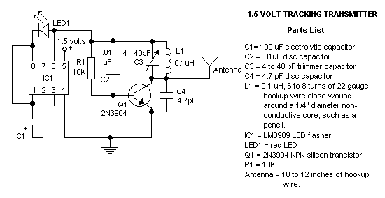
The described circuit utilizes a transistor-based oscillator configuration, commonly employed in FM transmitter applications. The operation of this circuit hinges on the interaction between the transistor and an LC tank circuit, which consists of an inductor (L) and a capacitor (C) connected in parallel or series. This arrangement is crucial for generating the oscillatory signal required for frequency modulation.
During the conduction phase, which lasts for approximately 60-90 electrical degrees of the input signal, the transistor allows current to flow through the LC tank circuit. This current flow energizes the inductor and capacitor, resulting in the storage of energy within the tank circuit. When the transistor turns off, the stored energy in the inductor and capacitor causes the circuit to oscillate, producing a sinusoidal waveform. This oscillation is critical for generating the carrier wave necessary for FM transmission.
The efficiency of this circuit, reported to be between 77-85%, is significantly higher than that of linear oscillators, which typically achieve efficiencies of only 40-50%. This higher efficiency is attributed to the switching nature of the transistor operation, which minimizes power loss during the conduction and cutoff phases.
The output of the oscillator is coupled to an antenna, allowing the generated RF signal to be transmitted over the air. The quality of the output waveform is essential for effective transmission, as it influences the modulation characteristics and overall performance of the FM transmitter. Proper tuning of the LC tank circuit is necessary to ensure that the oscillator operates at the desired frequency, providing optimal transmission characteristics.
In summary, this circuit exemplifies an efficient method for generating FM signals, leveraging the properties of a transistor and an LC tank circuit to produce a robust and effective transmission output.The circuit is a common form used in FM transmitters. The transistor conducts for 60-90 electrical degrees. When it turns off the LC tank `rings`, completing the sinusoidal waveform coupled to the antenna. The circuit is 77-85% effecient, compared to 40-50% for a linear oscillator. 🔗 External reference
Related Circuits
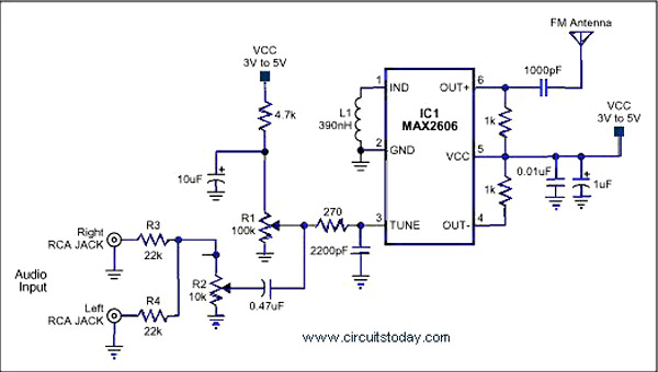
A simple single-chip FM transmitter circuit with a diagram and schematic using the IC MAX 2606, which is a high-performance voltage-controlled oscillator (VCO). The FM transmitter circuit utilizing the MAX 2606 is designed for efficient frequency modulation of audio signals....
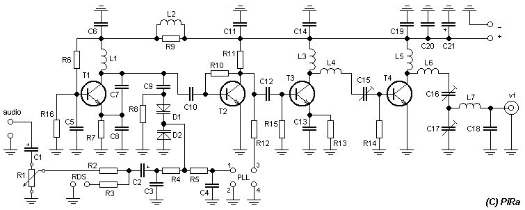
Connect two 24 V / 3 W bulbs in parallel to the output and set the right frequency on PLL. Now turn on the transmitter. You should tune it on a receiver. Maybe you might stretch coils of the...
A 40kHz ultrasonic transmitter circuit consists of three oscillators (F1, F2, and F3), with F3 generating a 40kHz square wave output. The frequency is primarily determined by components C1, R1, and an adjustable resistor (RP). The excitation output from...
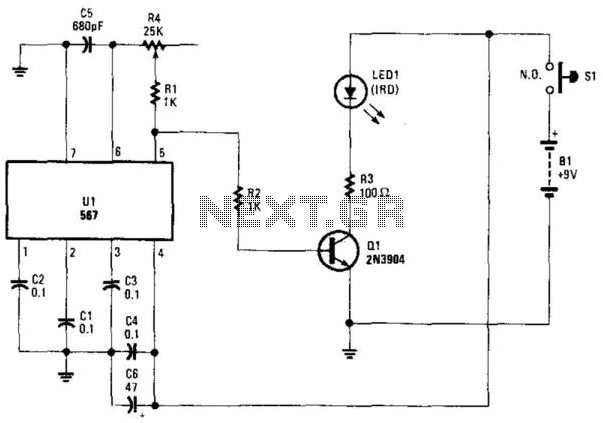
Using an NE567 as a tone oscillator, this circuit produces an infrared (IR) signal from the LED, which is modulated with a square wave. LED1 is an IR-emitting LED. The modulation enhances performance under high ambient light conditions. The circuit...
The W7800 is a positive integrated voltage regulator, while the F007 consists of an operational amplifier used in a power supply tracking application circuit. Some configurations utilize both positive and negative power supplies, with a negative supply necessary to...
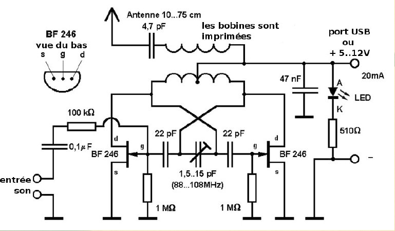
This compact FM transmitter is designed for connection to a USB port and has a range of approximately 50 meters. It can be utilized alongside multiple mini-transmitters to create a diverse and engaging radio program. The power supply through...
Warning: include(partials/cookie-banner.php): Failed to open stream: Permission denied in /var/www/html/nextgr/view-circuit.php on line 713
Warning: include(): Failed opening 'partials/cookie-banner.php' for inclusion (include_path='.:/usr/share/php') in /var/www/html/nextgr/view-circuit.php on line 713