
W7800 by the application circuit composed of power supply tracking
The W7800 voltage regulator is designed to provide a stable output voltage, making it suitable for various applications where a consistent power supply is critical. Its integration allows for reduced component count and improved reliability in electronic circuits. The F007 operational amplifier complements the W7800 by enabling precise tracking of the output voltage, which is particularly important in systems where the positive and negative supplies must remain in sync.
The operational amplifier in the F007 configuration is connected in a feedback loop that monitors the output voltage of the W7800. By utilizing high-precision resistors, the circuit achieves accurate control over the output, ensuring that any variations in the positive supply are mirrored by the negative supply. This tracking mechanism is essential in applications such as dual-supply op-amp circuits, where maintaining a balanced supply voltage is crucial for optimal performance.
In summary, the combination of the W7800 and F007 creates a robust solution for power supply regulation, where both positive and negative voltages are managed efficiently. The design emphasizes precision and stability, making it an ideal choice for sensitive electronic systems that require reliable power management. As shown in FIG W7800 is positive Integrated voltage regulator and F007 consisting of an operational amplifier power supply tracking application circuit. Some use positive and negative of the power supply, a negative supply required to track changes in the positive supply. Figure W7800 do with the positive supply, operational amplifiers and power tubes can be traced negative supply. Shown by two identical (higher precision) of 4.7 k resistor, the potential of the F007s control inputs at zero level, and the output of the F007 with the power to control the negative loop regulator to maintain the output of the negative positive output tracking.
F007 op amp power supply with positive and negative input voltage source.
Related Circuits
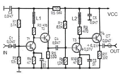
This antenna amplifier is effective for the frequency range of 35 kHz to 150 MHz. The circuit utilizes transistors and features a low 3 dB non-linearity along with a high gain of 43 dB. The input and output impedance...
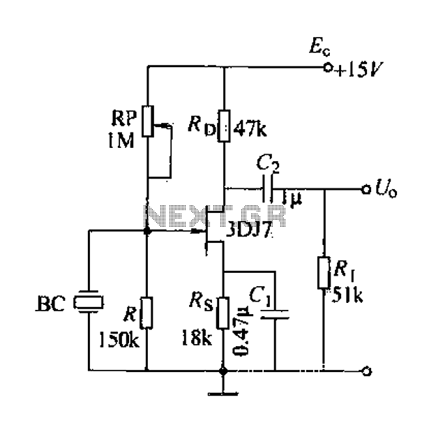
A field effect transistor (FET) voice amplifier has a low input impedance, approximately 1 kΩ, requiring the signal source to provide a constant current signal for operation. Unlike bipolar transistors, FETs are voltage-controlled devices that draw minimal current at...
The goal is to create a small light that is activated by motion and stays illuminated for 20 seconds before turning off. For example, when the light is picked up, it illuminates, and when placed back down, it remains...
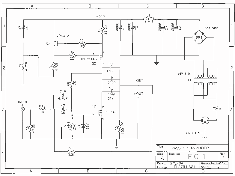
The Zen single-ended MOSFET amplifier was published by Nelson Pass in The Audio Amateur. In a subsequent issue of this magazine, Nelson slightly improved the original design. The "Revisited" version includes the following circuit modifications: 1. More extensive power supply...
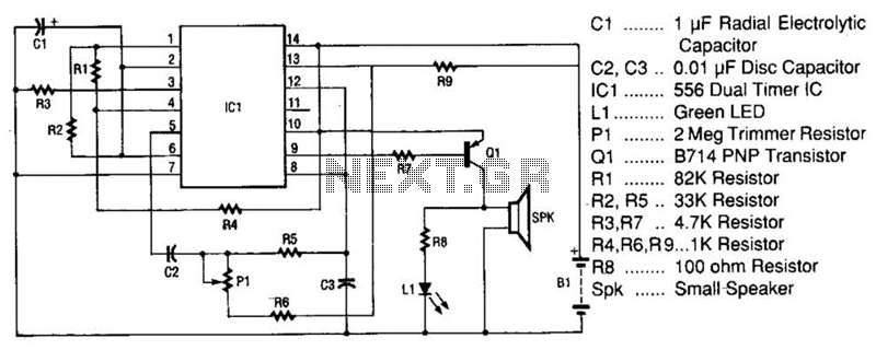
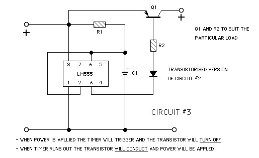
The space-age sound device utilizes a 556 dual timer integrated circuit (IC) to generate a phasor sound. This IC consists of two 555 timer circuits within a single 14-pin package, as depicted in the schematic. Each timer operates in...
Figure 4-52 (a) illustrates the two-phase wiring for direct current (DC) operation, while Figure 4-52 (b) depicts the two-phase current differential wiring for alternating current (AC) operation. The schematic in Figure 4-52 (a) represents a two-phase wiring configuration suitable for...