
Ir Transmitter
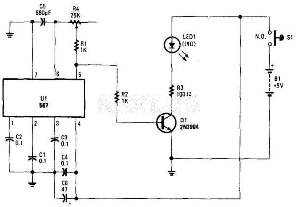
The circuit employs an NE567 phase-locked loop (PLL) integrated circuit, which is configured to function as a tone oscillator. The NE567 generates a square wave output, which is crucial for modulating the infrared signal emitted by LED1. This modulation allows the IR signal to be transmitted more effectively, particularly in environments with significant ambient light interference, which can often cause issues in IR communication systems.
The LED1, an infrared-emitting diode, is driven by the output of the NE567. When the NE567 operates, it produces a square wave that rapidly turns the LED on and off, creating a pulsed IR signal. This pulsing action is essential for encoding data onto the IR signal, facilitating communication with compatible receivers that can demodulate the signal back into its original form.
In addition to the NE567 and LED1, passive components such as resistors and capacitors may be included in the circuit to set the frequency of oscillation and stabilize the operation of the NE567. The choice of these components will directly influence the modulation frequency and the overall performance of the circuit. Proper selection is crucial to ensure that the modulation frequency remains within the optimal range for the intended application.
Furthermore, the implementation of this circuit design allows for improved signal integrity in environments where ambient light can mask or distort the IR signals. By utilizing modulation techniques, the circuit can achieve reliable communication over varying distances and under different lighting conditions, making it suitable for various applications, including remote controls and data transmission systems in consumer electronics. Using an NE567 as a tone oscillator, this circuit produces an IR signal from the LED, which is modulated with a square wave. LED1 is an IR-emitting LED. The modulation helps improve performance under high ambient light conditions. 🔗 External reference
Related Circuits
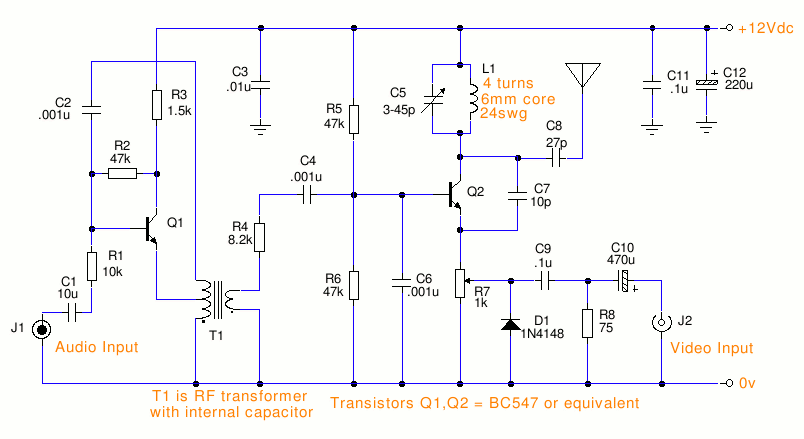
This is a small TV transmitter circuit that transmits in VHF, utilizing negative sound modulation and PAL video modulation. It is suitable for countries that use the B and G system. T1 refers to a type of transformer. The...
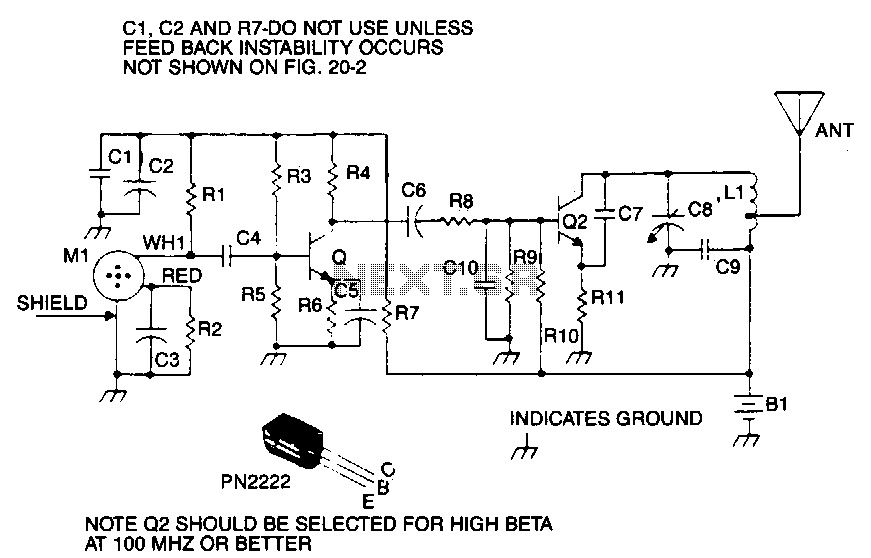
This is a sensitive, mini-powered FM transmitter that includes an RF oscillator section integrated with a high-sensitivity wide passband audio amplifier and a capacitance microphone featuring a built-in FET. The microphone modulates the base of the RF oscillator transistor....
3-3.5 Watt FM Transmitter. This is the schematic for an FM transmitter with 3 to 3.5 W output power that can be used between 90 and 110 MHz. Although the stability is not so bad, a. The 3-3.5 Watt FM...
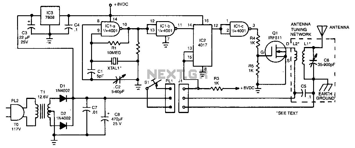
The crystal oscillator utilizes two sections of IC1, a 4001 quad 2-input NOR gate, representing a standard and reliable design. The oscillator generates a 1.85-MHz square-wave output that feeds into IC2, a 4017 divide-by-10 counter. The count enable and...
An FM modulator that modulates a carrier frequency with the composite signal, and an RF amplifier that provides enough power to be transmitted through an antenna. Here is the schematic diagram of the FM transmitter circuit: The core of...
The transmitter described here includes an additional RF power amplifier stage following the oscillator stage, which increases the output power to 200-250 milliwatts. When connected to a properly matched 50-ohm ground plane antenna or a multi-element Yagi antenna, this...
Warning: include(partials/cookie-banner.php): Failed to open stream: Permission denied in /var/www/html/nextgr/view-circuit.php on line 713
Warning: include(): Failed opening 'partials/cookie-banner.php' for inclusion (include_path='.:/usr/share/php') in /var/www/html/nextgr/view-circuit.php on line 713