
1-Chip 4-Channel PIC16F886 Data Logger
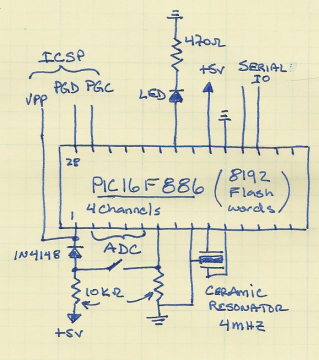
The project utilizes the PIC16F886 microcontroller, which serves as the core of the data logging system. This microcontroller is chosen for its compatibility with the previous version (PIC16F876) while offering enhanced features. The schematic includes connections for the hardware serial I/O channels, specifically pins 17 (TX) and 18 (RX), which facilitate communication with external devices. The indicator LED is connected to a designated pin to visually indicate when data logging is active, providing real-time feedback to the user.
The switch integrated into the design allows for easy toggling between two operational modes: logging data and transmitting logged data over the serial port. This flexibility is crucial for applications where data needs to be reviewed or transferred to another system without reprogramming the device.
The software component of the project is developed using the CCS compiler, which simplifies the process of accessing program memory. The commands for reading and writing to EEPROM are user-friendly, enabling efficient data handling. The total program memory of 8192 words allows for substantial data logging capabilities, and the logging duration can be adjusted through the delay settings within the code, specifically at line 64 of main.c.
To determine the optimal logging interval, a frequency counter can be employed at the indicator LED. This method allows for precise adjustments to the logging frequency, ensuring that the data collection meets the specific needs of the application. Furthermore, by modifying the START_ADR to the lowest open memory address, users can maximize the available memory for logging without the need for extensive code alterations.
The physical assembly of the logger includes an LM35 temperature sensor, which is positioned to measure ambient temperature accurately. The 7805 voltage regulator ensures that the microcontroller and other components receive a stable 5V supply from the 9V battery, making the system portable and reliable for various logging applications. This combination of hardware and software provides a robust solution for data logging tasks in a wide range of environments.This project has only a few modifications from the Single Chip, Four Channel Datalogger article, so I won`t go into much detail. Below is the schematic. The changes from Dan`s datalogger are that I used the PIC16F886, which is pin-compatible with the PIC 16F876.
I also used the PI`s hardware serial I/O channels (pins 17 and 18) and I added Can indicator LED that indicates logging in progress and the log interval (pin 22). The switch sets the mode between logging and writing data over the serial port. The C data logger code is available here as is a hex file with 1 s log interval. I used the CCS compiler. This makes reading and writing program memory very straight forward with commands like write_program_eeprom( prog_mem_adr, value ) and read_program_eeprom(prog_mem_adr). The 16F886 has 8192 total program flash words. The total time of logging is determined by the delay setting at line 64 of main. c. Use a frequency counter at the indicator LED to set the desired logging interval. If you don`t add any lines to the code, you can increase the memory used for logging by setting START_ADR to the lowest open memory address.
You can get this information with, e. g. , the PICKit2 programming application or whatever your favorite PIC programmer provides. Here`s the completed logger with a LM35 temperature sensor (suspended in the foreground) and a 7805 regulator (on the back left corner of the board) with a 9V battery attached. 🔗 External reference
Related Circuits
A typical circuit for applications such as mobile phones, MP3 players, and portable electronics utilizing the SSM2602 Low Power Audio Codec is provided in the SSM2602 Applications Circuit Schematic. The SSM2602 Low Power Audio Codec is designed for high-performance audio...
The UC3825 IC, manufactured by Texas Instruments, is a high-speed pulse width modulation (PWM) controller that serves as the central processor for a DC/DC converter control circuit. This circuit primarily consists of three integrated circuits: the UC3825BN, ISO124, and...
This project implements a USB device that provides a real-time clock for time-stamping events in a non-networked embedded computer environment. For embedded applications requiring periodic time-stamping (such as entry-system logs and configuration audit logs), an accurate real-time clock is...
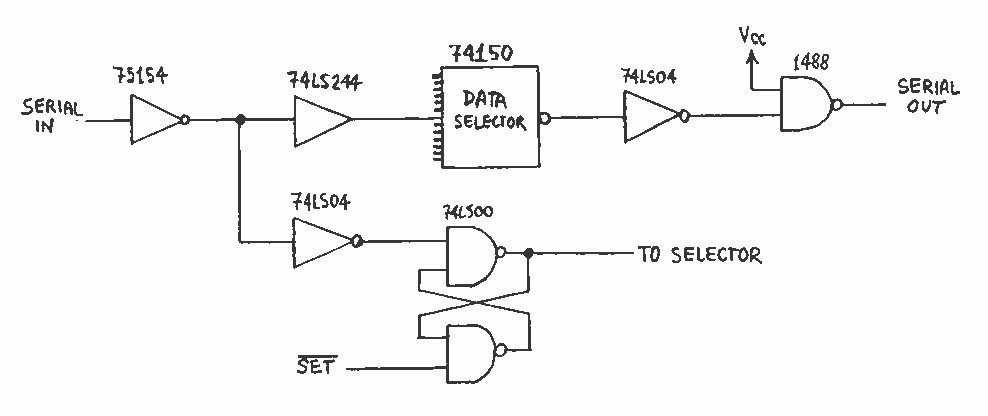
This report deals with the design for a small asynchronous serial data switch. The switch architecture allows 14 serial ports supporting a subset of the RS-232 protocol. The requirements for the switch are discussed. The hardware interfaces are described...

This 4-channel commutator utilizes the 2N4091 to achieve a low channel ON resistance (approximately 30 ohms) and minimal OFF current leakage. The DM7800 voltage translator is a monolithic device that provides gate drive voltages ranging from 10V to 20V...
The Vinculum board is controlled using DOS commands. Each time a command is sent, if executed successfully, the board responds with "D:>", indicating readiness for the next command. Sending commands faster than the Vinculum board can execute them, without...