
RS-232 Data Switch
It is recommended that an improved switching network design be investigated, that the software functionality be enhanced to allow better security, and that CMOS integrated circuits be used to reduce heat dissipation. More: It was found that a 3-wire serial interface would be sufficient for each of the data ports. Two additional status lines were implemented mainly for the use of the switch. The remaining status lines were tied to the appropriate logic levels with resistors. It was found to be trivial to make the ports immune to damage due to wiring errors. It was decided that requesting the switch's attention should be done via the serial data line. The only serial activity which the switch can monitor on all lines simultaneously is a break signal. This was used. The length of the break signal required was made configurable, so if it is possible to produce variable length break signals, short ones can be sent without dropping into command mode.
A considerable amount of hardware was needed to build a six port version of the switch. Thirty-four IC packages were needed. Implementing the remaining eight ports would require another twenty-six IC packages.
Due to the requirements for the switch processor, it was possible to implement a real-time clock/calendar at zero hardware cost. Since the switch will be powered up at all times, this will be a useful feature.
RECOMMENDATIONS
It is recommended that the switch software be expanded to provide complete security provisions, so it can be used in a less secure environment than that originally aimed for. Most of the required functionality is already in the software. A more elegant solution to the switching network problem should be investigated. At present, the network would require 23 integrated circuits to implement fully, whereas a more sophisticated version using crosspoint switches might only require 5. However, an inexpensive source of the crosspoint switches would have to be found.
Finally, it is recommended that lower power versions of the CPU and EPROM be used. These are available at higher cost, but would reduce heat dissipation.
1. INTRODUCTION
When a collection of small computers and their peripherals is used, a need often exists to establish serial connections between pieces of equipment. Usually, there is a modem attached to a telephone line, and this modem needs to be connected to different computers at different times. Sometimes, it is necessary to interconnect computers to transfer files, as they have incompatible disk formats. At other times, a computer or terminal is used to control or download code to a system under development. A property of this type of connection is that it needs to be modified often. Unfortunately, serial port connectors tend to be located on the least accessible portion of any piece of equipment, not all cables work with all equipment, and sometimes it is risky to switch cables while equipment is powered up.
To solve these problems, a fully automatic RS-232 data switch was developed. The switch has well-defined interfaces of both DCE and DTE types, which will connect to virtually any serial port using standard cables. Once the cables are in place, they need not be moved again. The switch is fully intelligent and can be controlled from any of its ports. As well, it provides functions not possible with serial cables, such as dial-in access from the modem to any serial device connected, time and date, and unusual connections such as broadcast and ring capabilities.
In this report, the requirements for this switch are gathered, and a complete implementation is presented. It will be seen that the design is optimized for personal use, and low cost of production in small quantities. A software user's manual is included.
2. REQUIREMENTS
2.1 Operating Environment
The data switch is intended for interconnection of computer equipment in a single room. This means that all the equipment will be under control of a small group of individuals or single person, who also maintains the switch. A typical application might include a modem, a couple of personal computers, a line to a host computer, a dumb terminal, and a line to the terminal port of a system without an integral video display. The number of ports should be in line with this requirement. The architecture must support on the order of 10 ports, but beyond this, cost dictates what the maximum will be.
Security provisions should be minimal, but must be sufficient to allow a dial-in modem, or publicly accessible terminal, to be connected to the switch without giving it full access. This necessitates different levels of access, and passwords to switch between them. The switch should be a standalone device. It should not rely on the resources of any devices attached to it, that is, it should have its own intelligence, and a dumb terminal should be enough to control it. The switch will be considered part of the behind-the-scenes wiring between equipment, rather than part of the equipment itself. As such, it needs no switches, lights, or any other I/O devices other than the data ports. It will be powered up all the time, so it needs no nonvolatile memory of any kind. In the event of a power failure, the switch configuration will simply be reloaded by sending a file of commands from an attached computer.
2.2 Interfaces
The switch must provide a number of RS-232 compatible serial ports. Since there are two major types of these (DCE and DTE), it should provide both. Ideally, there should be no cabling difficulties, that is, virtually any piece of equipment should be connectable with standard off-the-shelf cables. The switch should not be damaged when a cable is accidentally plugged into the wrong type (DCE/DTE) of port. The main goal of the switch is to connect asynchronous serial data, that is, to route the TxD and RxD signals between the ports. It will not be feasible to deal with the remaining signals, but the well-defined outputs should be tied to the appropriate logic levels when not otherwise controlled, to provide valid interfaces.
Beyond the TxD and RxD lines, it is desirable to have an additional input and output line on a port. It is then possible to pass the input through to the output at the other end of the connection, and thus route DTR and carrier detect signals as well as data. Since the DTR input from a terminal and the carrier detect output from a modem both indicate that the equipment is on and communicating, the status of these inputs can be used by the switch software to provide some intelligent features.
Since the switch and most of its peripherals will be located in a single room, providing robust data interfaces is not a problem. Standard RS-232 ports will suffice, with no major concern placed on noise immunity and such factors. It is up to the user to provide current loop converters and whatever else necessary if a terminal does have to be located remotely.
Since the RS-232 interfaces provided by the switch are simple and generic, an equally simple and generic method is needed to obtain the attention of the switch when a port wishes to send it a command. The choice is between signaling in-band using the RS-232 data lines, or out-of-band using an extra input or the DTR line. In-band signaling is preferred, since it allows even terminals with three wire interfaces, and users connected via a modem, to get into command mode. Unfortunately, hardware to detect in-band attention signals on all the ports can become very complex. A reasonable compromise seems to be to detect an RS-232 "break" signal as the attention code.
2.3 Cost Issues
A primary factor in the design of the switch is cost. The switch will not be produced in quantity, therefore, what is built should use standard, low-cost components. It is obvious from the earlier requirements that a microprocessor is needed to control the switch. This should be a microcontroller of a type making it possible to build an intelligent control core from a few simple parts. Processing power and memory capacity beyond a few kilobytes are not an issue. Ease of software development is an issue because it affects development time, which is a major cost because the switch will not be built in quantity. One software development feature which should exist is the ability to download experimental firmware into the switch and run it without having to program an EPROM. This vastly decreases the turnaround time for debugging, but requires spare RAM on the same order of magnitude as the EPROM for the code, and the ability to execute code from the RAM.
2.4 Other Requirements
The simple hardware intended for the switch will make it impossible to provide a command-mode session for more than one port at a time. This becomes an issue when a terminal is remotely located, or a user is calling in on the modem, and wishes to get into command mode when the processor is already busy serving another port. A system of timeouts must be provided which makes the expected waiting time for command mode fairly small and results in a reasonable worst-case waiting time. At the same time, it must be possible to complete a command mode session even when another user is waiting. The switch should be able to act transparent for equipment and/or users which are unable to deal with it. For example, it should be possible to route an incoming call on a dial-in modem to another port without intervention from the caller. An automatic connection feature will be provided, so that the modem port can be configured to connect to another port automatically as soon as its carrier detect input becomes asserted.
Finally, it is judged desirable that the switch maintain the time and date. Since it runs continuously and its processor needs to maintain timers anyway, this comes at the cost of only a small amount of software. But it allows computers which have no battery backed-up clocks to query the switch for the time and date at startup.This report deals with the design for a small asynchronous serial data switch. The switch architecture allows 14 serial ports supporting a subset of the RS-232 protocol. The requirements for the switch are discussed. The hardware interfaces are described in detail, and the software function is described in the form of a user's manual. Finally, the hardware and software implementation is presented. It is concluded that though low-cost, the hardware design is excessively complex. It is found that the simple 3-wire serial interface is sufficient for most applications, and that an RS-232 "break" signal is ideal for obtaining the switch processor's attention.
It is seen that a clock/calendar capability could be added at zero cost to the switch design. It is recommended that an improved switching network design be investigated, that the software functionality be enhanced to allow better security, and that CMOS integrated circuits be used to reduce heat dissipation. It was found that a 3-wire serial interface would be sufficient for each of the data ports. Two additional status lines were implemented mainly for the use of the switch. The remaining status lines were tied to the appropriate logic levels with resistors. It was found to be trivial to make the ports immune to damage due to wiring errors. It was decided that requesting the switch's attention should be done via the serial data line. The only serial activity which the switch can monitor on all lines simultaneously is a break signal. This was used. The length of the break signal required was made configurable, so if it is possible to produce variable length break signals, short ones can be sent without dropping into command mode. A considerable amount of hardware was needed to build a six port version of the switch. Thirty-four IC packages were needed. Implementing the remaining eight ports would require another twenty-six IC packages. Due to the requirements for the switch processor, it was possible to implement a real time clock/calendar at zero hardware cost.
Since the switch will be powered up at all times, this will be a useful feature. RECOMMENDATIONS It is recommended that the switch software be expanded to provide complete security provisions, so it can be used in a less secure environment than that originally aimed for. Most of the required functionality is already in the software. A more elegant solution to the switching network problem should be investigated. At present, the network would require 23 integrated circuits to implement fully, whereas a more sophisticated version using crosspoint switches might only require 5.
However, an inexpensive source of the crosspoint switches would have to be found. Finally, it is recommended that lower power versions of the CPU and EPROM be used. These are available at higher cost, but would reduce heat dissipation. 1. INTRODUCTION When a collection of small computers and their peripherals is used, a need often exists to establish serial connections between pieces of equipment. Usually, there is a modem attached to a telephone line, and this modem needs to be connected to different computers at different times.
Sometimes, it is necessary to interconnect computers to transfer files, as they have incompatible disk formats. At other times, a computer or terminal is used to control or download code to a system under development.
A property of this type of connection is that it needs to be modified often. Unfortunately, serial port connectors tend to be located on the least accessible portion of any piece of equipment, not all cables work with all equipment, and sometimes it is risky to switch cables while equipment is powered up. To solve these problems, a fully automatic RS-232 data switch was developed. The switch has well-defined interfaces of both DCE and DTE types, which will connect to virtually any serial port using standard cables.
Once the cables are in place, they need not be moved again. The switch is fully intelligent and can be controlled from any of its ports. As well, it provides functions not possible with serial cables, such as dial-in access from the modem to any serial device connected, time and date, and unusual connections such as broadcast and ring capabilities. In this report, the requirements for this switch are gathered, and a complete implementation is presented.
It will be seen that the design is optimized for personal use, and low cost of production in small quantities. A software user's manual is included. 2. REQUIREMENTS 2.1 Operating Environment The data switch is intended for interconnection of computer equipment in a single room.
This means that all the equipment will be under control of a small group of individuals or single person, who also maintains the switch. A typical application might include a modem, a couple of personal computers, a line to a host computer, a dumb terminal, and a line to the terminal port of a system without an integral video display.
The number of ports should be in line with this requirement. The architecture must support on the order of 10 ports, but beyond this, cost dictates what the maximum will be. Security provisions should be minimal, but must be sufficient to allow a dial-in modem, or publicly accessible terminal, to be connected to the switch without giving it full access.
This necessitates different levels of access, and passwords to switch between them. The switch should be a standalone device. It should not rely on the resources of any devices attached to it, that is, it should have its own intelligence, and a dumb terminal should be enough to control it. The switch will be considered part of the behind-the-scenes wiring between equipment, rather than part of the equipment itself.
As such, it needs no switches, lights, or any other I/O devices other than the data ports. It will be powered up all the time, so it needs no nonvolatile memory of any kind. In the event of a power failure, the switch configuration will simply be reloaded by sending a file of commands from an attached computer. 2.2 Interfaces The switch must provide a number of RS-232 compatible serial ports. Since there are two major types of these (DCE and DTE), it should provide both. Ideally, there should be no cabling difficulties, that is, virtually any piece of equipment should be connectable with standard off-the-shelf cables.
The switch should not be damaged when a cable is accidentally plugged into the wrong type (DCE/DTE) of port. The main goal of the switch is to connect asynchronous serial data, that is, to route the TxD and RxD signals between the ports.
It will not be feasible to deal with the remaining signals, but the well-defined outputs should be tied to the appropriate logic levels when not otherwise controlled, to provide valid interfaces. Beyond the TxD and RxD lines, it is desirable to have an additional input and output line on a port. It is then possible to pass the input through to the output at the other end of the connection, and thus route DTR and carrier detect signals as well as data.
Since the DTR input from a terminal and the carrier detect output from a modem both indicate that the equipment is on and communicating, the status of these inputs can be used by the switch software to provide some intelligent features. Since the switch and most of its peripherals will be located in a single room, providing robust data interfaces is not a problem.
Standard RS-232 ports will suffice, with no major concern placed on noise immunity and such factors. It is up to the user to provide current loop converters and whatever else necessary if a terminal does have to be located remotely. Since the RS-232 interfaces provided by the switch are simple and generic, an equally simple and generic method is needed to obtain the attention of the switch when a port wishes to send it a command.
The choice is between signaling in-band using the RS-232 data lines, or out-of-band using an extra input or the DTR line. In-band signaling is preferred, since it allows even terminals with three wire interfaces, and users connected via a modem, to get into command mode.
Unfortunately, hardware to detect in-band attention signals on all the ports can become very complex. A reasonable compromise seems to be to detect an RS-232 "break" signal as the attention code. 2.3 Cost Issues A primary factor in the design of the switch is cost. The switch will not be produced in quantity, therefore, what is built should use standard, low-cost components.
It is obvious from the earlier requirements that a microprocessor is needed to control the switch. This should be a microcontroller of a type making it possible to build an intelligent control core from a few simple parts. Processing power and memory capacity beyond a few kilobytes are not an issue. Ease of software development is an issue because it affects development time, which is a major cost because the switch will not be built in quantity.
One software development feature which should exist is the ability to download experimental firmware into the switch and run it without having to program an EPROM. This vastly decreases the turnaround time for debugging, but requires spare RAM on the same order of magnitude as the EPROM for the code, and ability to execute code from the RAM.
2.4 Other Requirements The simple hardware intended for the switch will make it impossible to provide a command-mode session for more than one port at a time. This becomes an issue when a terminal is remotely located, or a user is calling in on the modem, and wishes to get into command mode when the processor is already busy serving another port.
A system of timeouts must be provided which makes the expected waiting time for command mode fairly small and results in a reasonable worst-case waiting time. At the same time, it must be possible to complete a command mode session even when another user is waiting.
The switch should be able to act transparent for equipment and/or users which are unable to deal with it. For example, it should be possible to route an incoming call on a dial-in modem to another port without intervention from the caller.
An automatic connection feature will be provided, so that the modem port can be configured to connect to another port automatically as soon as its carrier detect input becomes asserted. Finally, it is judged desirable that the switch maintain the time and date. Since it runs continuously and its processor needs to maintain timers anyway, this comes at the cost of only a small amount of software.
But it allows computers which have no battery backed-up clocks to query the switch for the time and date at startup. 🔗 External reference
Related Circuits

The circuit below is similar to the one above but can be used with a laser pointer to toggle the relay rather than a push button. The IR photo transistor Q1 (Radio Shack 276-145A) or similar is connected to...
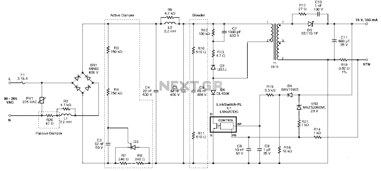
Power Integrations' DER322 reference design employs the LinkSwitch-PL family of LNK460VG devices. This design represents the industry's first alternative 100W A19 incandescent LED driver utilizing a single-layer PCB. It is characterized by low cost, minimal component count, and compact...
A precision oscillator can be constructed using a quartz crystal; however, with appropriate component selection, it is also possible to build one using an RC (resistor and capacitor) circuit. An RC oscillator generates an oscillating signal through the use of...
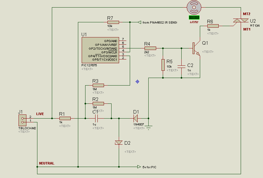
A project is underway to control the speed of an electric fan (220Vac, 60W, 5A max.) automatically using a microcontroller based on certain parameters. The circuit design for controlling the speed of an electric fan involves several key components to...
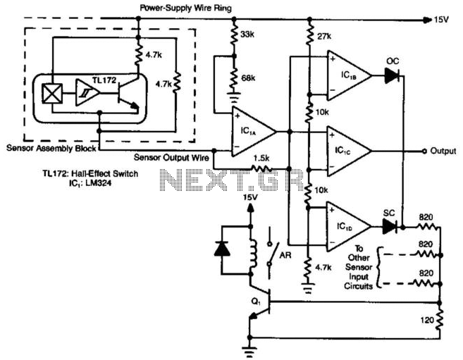
Hall-effect switches offer numerous benefits compared to mechanically and optically coupled switches. However, a significant disadvantage is their requirement for three wires per device. This circuit design reduces the wire count to N+1 wires for N devices. Amplifier IC1A...
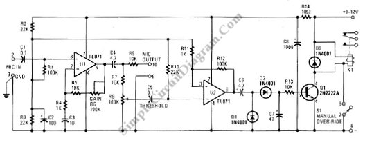
This schematic diagram below shows a circuit of a VOX Box (voice-operated switch). This circuit consists of a Schmitt trigger, a relay driver, and a microphone. The VOX Box circuit operates as a voice-activated switch, utilizing a microphone to detect...