
Secure USB Time-Stamp for Data-Logging
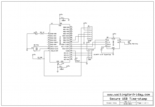
The schematic for the USB time-stamp device features the PIC18F2550 microcontroller at its core, which manages USB communication and interfaces with the DS1302 real-time clock through the SPI protocol. The DS1302 is connected to the microcontroller's SPI pins, allowing for efficient data exchange. The power supply circuitry includes the super-capacitor connected to the DS1302, ensuring that the clock remains operational during power interruptions. The USB interface is designed to facilitate easy connection to host systems, while the ICSP header enables firmware updates if required. The PCB layout is optimized for minimal space usage, with all components arranged to avoid the need for additional wire links or vias. This design choice enhances reliability and manufacturability. The LED indicator is connected to a GPIO pin on the PIC18F2550, providing a visual cue regarding the clock's operational status. Overall, this project represents a robust solution for time-stamping needs in embedded systems, combining accuracy, reliability, and ease of use in a compact design.This project implements a USB device which provides a real-time clock for the purpose of time-stamping events in an non-networked embedded computer environment. For embedded applications where a periodic time-stamp is required (such as entry-system logs, configuration audit logs, etc.
) it is necessary to have a fairly accurate real-time clock (bet ter than that typically provided by a PC`s motherboard) to generate time-stamps in logging and audit trails. Furthermore, it is preferable to have a method of confirming that the log/audit files have not been tampered with in anyway.
The secure USB time-stamp device solves many of these issues in a very small form factor using minimal components. The device logs the time at which the clock was last updated and (if requested by the USB host) the time when it last served a time-stamp.
This allows the host application to examine it`s own logs and compare them to the time values stored by the device (to detect when logs have been altered). The device stores the last time setting and the last logged time-stamp in the PIC`s non-volatile EEPROM memory which can hold the data for up to 40 years without battery backup.
The SUTS device is powered by a PIC18F2550 microcontroller which provides an on-board USB interface as well as the required SPI serial interface to the DS1302 real-time clock chip. To prevent loss of time setting when powered off or disconnected the DS1302 is backed up by a 0. 047F super-capacitor. A super-capacitor was chosen (rather than a lithium cell) since it is harder to remove (preventing a casual or deliberate reset of the time), charges very fast (less than 5 minutes from empty to fully-charged) and is capable of powering the RTC for around 90 hours without losing time.
Furthermore, the super-cap has a virtually unlimited lifespan and does not suffer from the restrictions placed on lithium devices (since it`s chemical make-up is more environmentally friendly). The PIC18F2550 requires an external oscillator in order to use the USB transceiver module, so a 20Mhz resonator with built in capacitors is used (since the DS1302 is responsible for time-keeping the PIC does not need a more expensive crystal oscillator).
An ICSP header is also included on the board, but can be omitted if the PIC is programmed and code-protected to prevent alteration of the firmware. The device is powered by the USB host connection and requires no external power-supply unit. The circuit board design is a single-layer PCB using only through-hole components to make it as easy as possible to duplicate.
No wire links or vias are required. Here is a picture of the PCB artwork which is included in the downloads section below: The firmware is completely written in Hi-Tech C and is based on my Open Source Framework for USB Generic HID devices based on the PIC18F and Windows. It is available for download in the downloads section below. The host passes the date and time to the device and the device sends the information to the DS1302, also the information is stored in the EEPROM for later retrieval (as the last date-time at which the clock was set) Once the device receives the command the current date-time of the DS1302 is passed back to the host including a `clock status` flag which is zero if the DS1302 has not been set (or has lost its time information due to depleted backup power) or one if the device is running normally.
The clock status flag lets the host know if the received data is valid or if it needs to set the clock (the clock status is also show by the LED on the device which is only lit after the clock is set). This command does not cause the device to log the date-time to EEPROM so can be used for regular fast-polling reads of the time.
This command is the same as 0x81 however it also causes the PIC to store the read date-time in EEPROM. The EEPROM is rated for approximately 1, 000, 000 write cycles with a retention span of >40 ye 🔗 External reference
Related Circuits
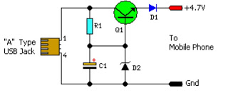
This simple circuit provides a regulated output of 4.7 volts for charging mobile phones. A USB outlet delivers 5 volts DC at a current of 100 mA, which is adequate for slow charging of mobile devices. Most mobile phone...
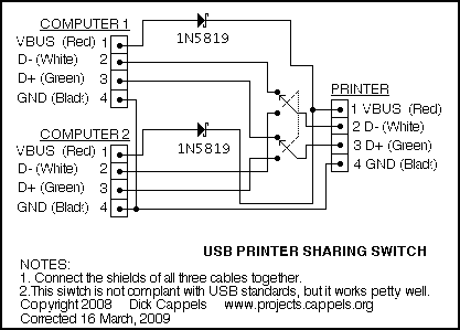
With a DPDT switch, I can switch the two data lines. I tried connecting the shields from the two computers together, the grounds two computers together, switching the D+ and D- lines with the DPDT switch, and leaving the...
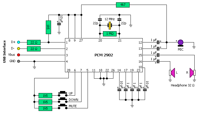
This USB circuit utilizes an integrated circuit (IC) to convert digital voice data into an analog format, making it suitable for headphone use. Additionally, the output can be amplified through a power amplifier, allowing the sound to be played...
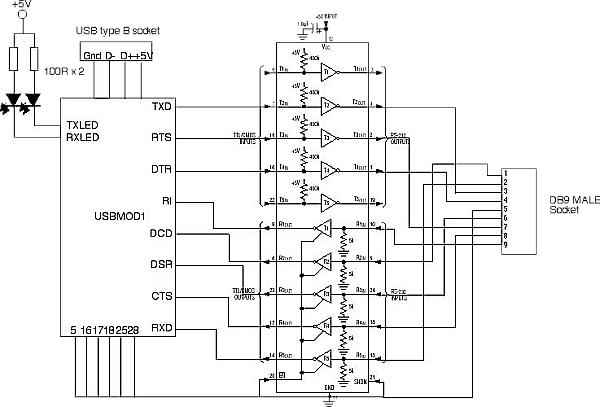
The FT8U232AM requires a small number of external components to produce a device that converts USB to TTL level RS232 signals. All that is needed is a TTL to RS232 converter to provide the 12V RS232 logic levels. The...

A Microchip PIC18F4550 microcontroller has been acquired, but there is uncertainty regarding its potential applications. Further research is needed to explore various possibilities for programming and utilizing the microcontroller, as well as integrating additional electronic devices with it. The Microchip...
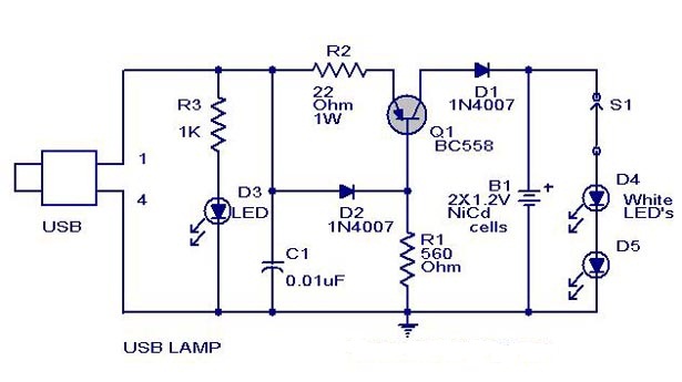
A simple USB-powered lamp designed to illuminate a desktop during power outages. The circuit operates at 5 volts sourced from a USB port. The 5V from the USB is directed through a current-limiting resistor (R2) and a transistor (Q1)....