
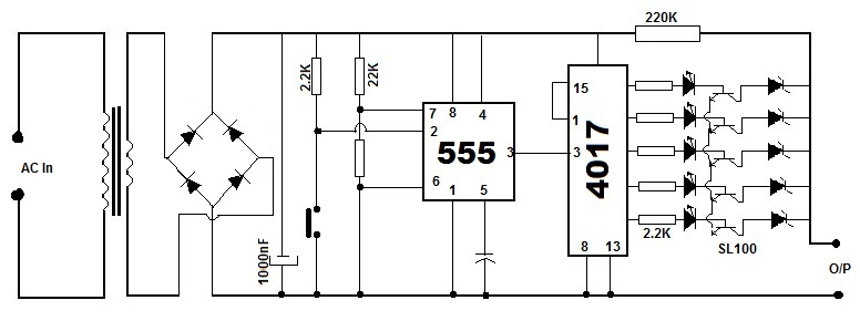
1 Hz Timebase by IC 4017
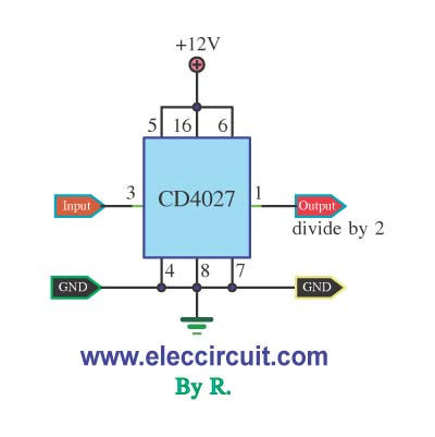
The 10-divider circuit can be implemented using various electronic components, including flip-flops, counters, and logic gates. A common approach is to use a series of flip-flops configured in a cascade arrangement. For instance, a binary counter composed of four flip-flops can be employed to achieve the desired division. Each flip-flop in the circuit toggles its output state with each clock pulse it receives, effectively dividing the frequency by two for each stage.
In this specific application, a square wave signal at 10 Hz serves as the input. The first flip-flop receives this signal and toggles its output at 5 Hz. The output of the first flip-flop is then fed into the second flip-flop, which further divides the frequency to 2.5 Hz. Continuing this process through additional flip-flops ultimately yields an output frequency of 1 Hz after the fifth flip-flop.
To enhance the reliability of the circuit, it is advisable to include debouncing circuitry if the input signal is derived from mechanical switches or contacts. Additionally, the circuit can be optimized for power consumption and response time, depending on the specific requirements of the application.
In summary, this 10-divider circuit effectively transforms a 10 Hz square wave input into a stable 1 Hz output, making it suitable for use in digital clocks and other timing applications.I used input frequency 10Hz to output 1Hz.This is a 10 divider circuit. When we need a standard digital clock 1 Hz. but we have the input signal is square wave.. 🔗 External reference
Related Circuits
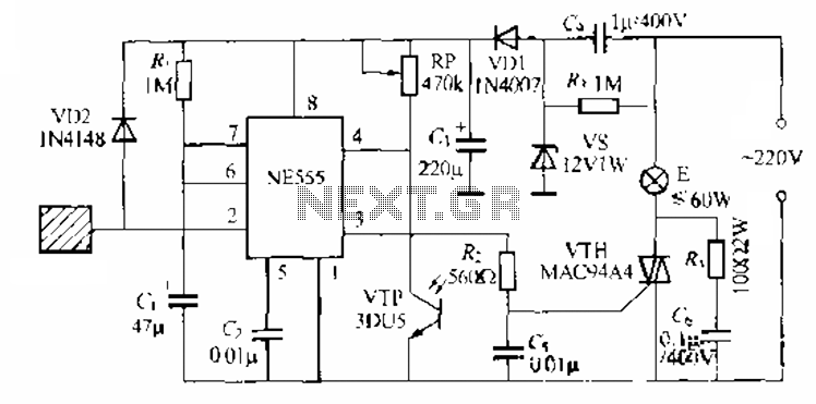
The circuit utilizes a NE553 automatic light sensor composed of 55 groups, allowing lights to turn on when individuals are present and turn off when they leave. The power supply includes VD1, vS, and C, with a 12V DC...
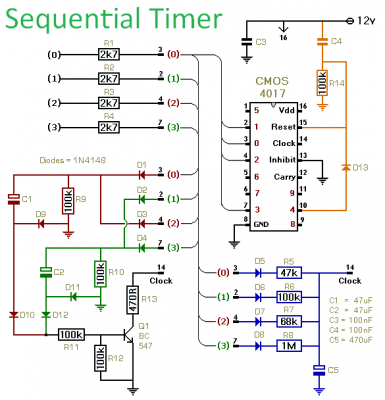
This timer is designed to manage a sequence of up to ten distinct events, with each event's duration adjustable independently. The sequence can either run for a predetermined number of cycles or continue indefinitely. Additionally, the individual events within...
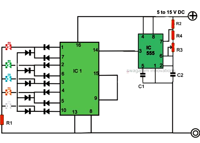
An LED light chaser circuit is an electronic configuration designed to illuminate a group of LEDs in a predetermined sequence. A commonly used integrated circuit (IC) for creating this type of LED sequencer circuit is the 4017. This IC...
Battery eliminators are circuits that create a DC power supply from AC mains. Essentially, battery eliminator circuits consist of a step-down transformer, rectifier, and voltage regulator. A simple circuit of a multipurpose battery eliminator features various output voltage ranges...
Christmas is approaching, and it is the time of year when electronics students and hobbyists consider creating a Christmas circuit for their homes, particularly one that features flashing lights. Numerous circuits and kits are available that can flash various...
Light emitting diodes are advantageous due to their smaller size, low current consumption and catchy colours they emit. Here is a running message display circuit wherein the letters formed by LED arrangement light up progressively. Once all the letters...