
Multipurpose Battery Eliminator Circuit using 4017 Decade Counter
Battery eliminators are essential for providing a stable DC voltage from an AC source, making them useful in various applications, including powering electronic devices that typically rely on batteries. The circuit begins with a step-down transformer that reduces the high AC voltage from the mains to a lower, manageable level. This lower AC voltage is then fed into a rectifier circuit, which converts AC to pulsating DC. The pulsating DC output is further smoothed using filtering capacitors to minimize voltage ripple, ensuring a more stable DC output.
The 555 timer IC, configured in monostable mode, generates a pulse signal that acts as a clock for the decade counter 4017. This counter effectively divides the pulse frequency to control the output voltage levels. Each output from the 4017 corresponds to a specific voltage level, which is selected by activating the appropriate transistor. The PNP transistors are configured to switch on and off based on the signals received from the decade counter. When a transistor is activated, it allows current to flow through a specific Zener diode, thereby regulating the output voltage to the desired level.
Zener diodes are critical components in this circuit, as they provide voltage regulation by maintaining a constant output voltage when reverse-biased. The selection of Zener diodes determines the output voltage levels available from the battery eliminator. This design allows users to obtain multiple output voltages, making the circuit versatile for various applications.
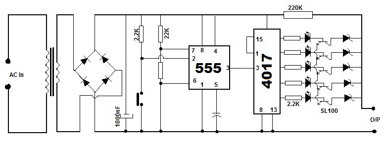
Overall, this multipurpose battery eliminator circuit efficiently converts AC mains power into a regulated DC output, offering flexibility in voltage selection while ensuring stable performance through the use of well-established electronic components.Battery Eliminators are the circuits, which creating DC power supply from AC Mains. Basically battery eliminator circuits are the compination of step down transformer, rectifier and voltage regulator. Here is a simple circuit of a Multipurpose Battery Eliminator, which has different range of out put voltages controlled by a decade counter 4017 ic
chip. First of all we need to convert AC to DC, which is doing by a Rectifier Circuit and we are creating a pulse generator using 555 timer IC wich is wired as Monostable mode After this the pulse is connecting to the decade counter 4017. Normally decade counter have ten out put shift register but here, in this circuit we are using only 5 out puts and 6th out is using to reset this shift register.
These out puts of the shift register are connected to the base of transistors, which is connected with voltage regulators (zener diods are used in this ciruit). In this circuit NE555 timer IC is wired as monostable miltivibrator and the third pin, out put pin of timer is connected to pin number 14 of 4017, which is the clock input.
Pin 3, 2, 4, 7 and 10 of 4017 is using outputs 1, 2, 3, 4 and 5 respectively. The sixth out put pin 1 is connected to the reset pin (15). Then the SL100, the PNP transistors are using to switch between diffrent voltages by diffrent voltage Zener Diodes. Each transistors will conncted while getting base voltage from 4017 and entire zener will be connected as voltage regulator.
🔗 External reference
Related Circuits
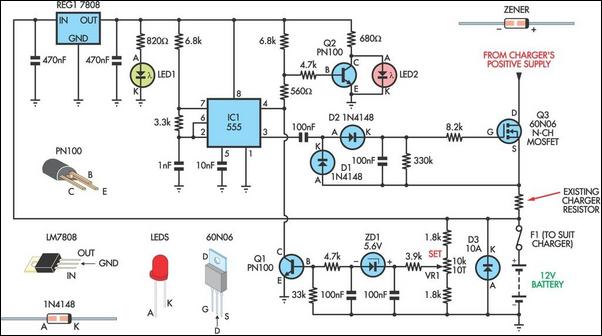
Most commercially available car battery chargers should not be connected to the battery for extended periods, as this can lead to overcharging and subsequent battery damage. This add-on circuit is connected in series with the battery being charged and...
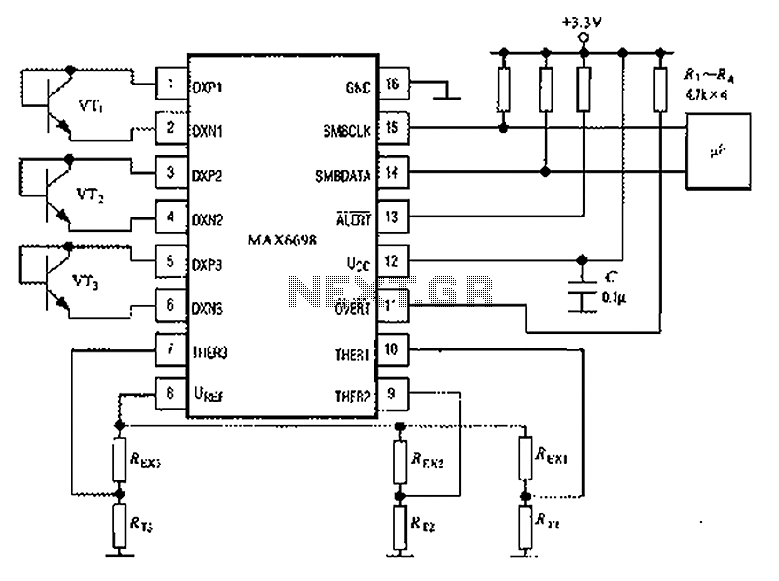
The circuit illustrated in the figure involves the MAX6698 maximum temperature sensor, which utilizes three transistors (VT1 to VT3) and three thermistors (RT1 to RT3). An internal reference voltage source is connected through resistors UREF REX1 to REX3, providing...
The circuit depicted will automatically switch ON and OFF at night and morning, respectively. In this circuit, R1 can be adjusted to change the sensitivity. The operation of the circuit is straightforward. The Light Dependent Resistor (LDR) exhibits very...
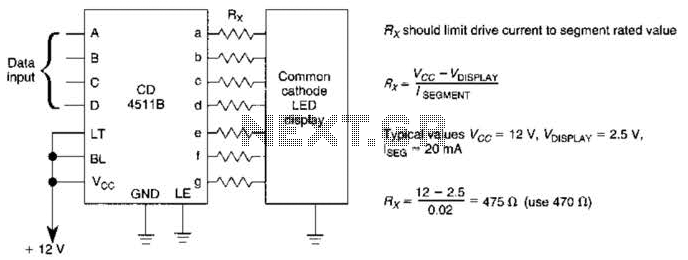
A CD4511B CMOS LED display driver can be utilized to operate a common cathode LED display. Current limiting resistors are employed to restrict the segment current to the specified value at the maximum supply voltage. The CD4511B is a...
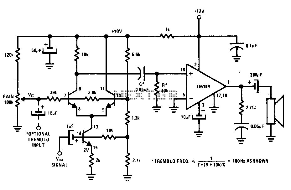
The transistors create a differential pair with an active current-source tail. This configuration, referred to as a variable-transconductance multiplier, produces an output that is proportional to the product of the two input signals. The multiplication effect arises from the...
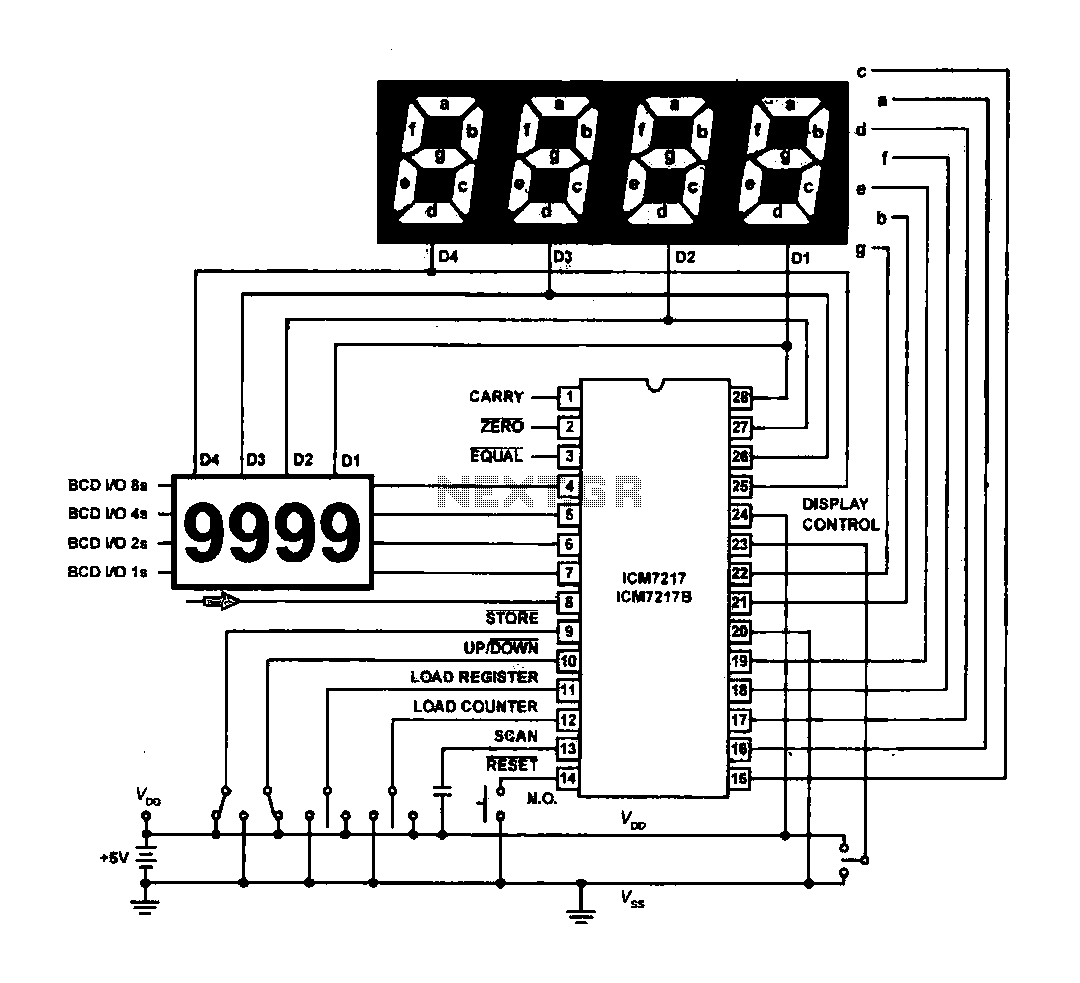
The circuit drives the light-emitting diode in a digital display configuration. The count signal is fed into the ICM7217 chip, which processes the count and subsequently drives the digital display board. The connection between the thumbwheel switches is illustrated...
Warning: include(partials/cookie-banner.php): Failed to open stream: Permission denied in /var/www/html/nextgr/view-circuit.php on line 713
Warning: include(): Failed opening 'partials/cookie-banner.php' for inclusion (include_path='.:/usr/share/php') in /var/www/html/nextgr/view-circuit.php on line 713