
10.7Mhz sweep generator
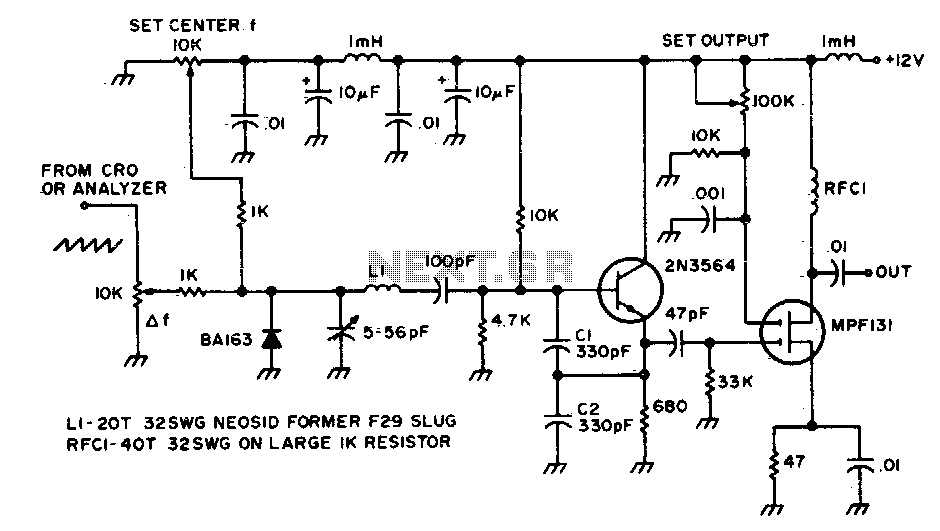
The circuit designed for observing the response of an IF amplifier or filter typically includes several key components that facilitate accurate measurement and analysis of the signal characteristics. At its core, the circuit may consist of a signal source, the IF amplifier or filter under test, and a measurement device such as an oscilloscope or spectrum analyzer.
The signal source generates a test signal, which is fed into the input of the IF amplifier or filter. This component is crucial as it determines the frequency response of the circuit being tested. The IF amplifier is designed to amplify signals at a specific frequency range, while the filter selectively allows certain frequencies to pass while attenuating others.
After the signal has passed through the IF amplifier or filter, it is directed to the measurement device. An oscilloscope is commonly used for time-domain analysis, allowing the user to visualize the waveform of the output signal and assess parameters such as amplitude, frequency, and phase shift. For more comprehensive frequency-domain analysis, a spectrum analyzer can be utilized. This device provides a graphical representation of the signal's frequency components, enabling detailed examination of the circuit's performance across a wider dynamic range.
Additional components such as resistors, capacitors, and possibly inductors may be incorporated into the circuit to ensure stability, reduce noise, and improve the overall performance of the measurement setup. Proper grounding and shielding techniques should also be employed to minimize interference and enhance measurement accuracy.
In summary, this circuit serves as a valuable tool for engineers and technicians to evaluate the performance of IF amplifiers and filters, providing insights that are essential for the design and optimization of communication systems and signal processing applications.This circuit is used to observe the response of an if amp or a filter It can be used with an oscilloscope or, for more dynamic range, with a spectrum analyzer. 🔗 External reference
Related Circuits
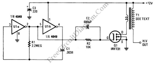
The schematic diagram below illustrates a circuit for a high voltage generator. This circuit employs a 4049 hex inverter as an oscillator, and it can be utilized for ignition purposes. The high voltage generator circuit is designed to convert a...
A function generator that operates within a frequency range of 0.1 Hz to 20 MHz can be constructed using the MAX038 integrated circuit chip. This represents a straightforward implementation of a high-performance signal generator. The MAX038 is a high-speed precision...
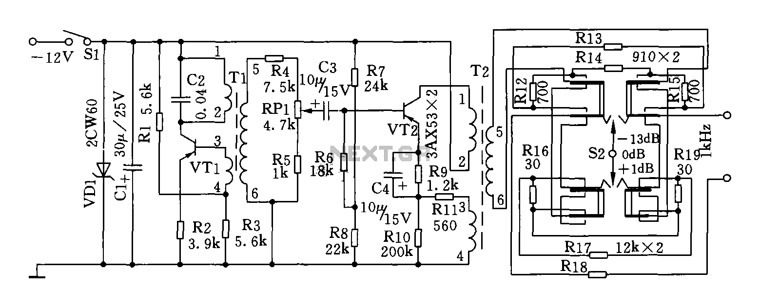
This circuit can generate a signal of 1 kHz and offers three output level options. It is suitable for testing communication equipment maintenance and barriers, providing a quick and accurate method to identify points of failure in televisions, stereos,...
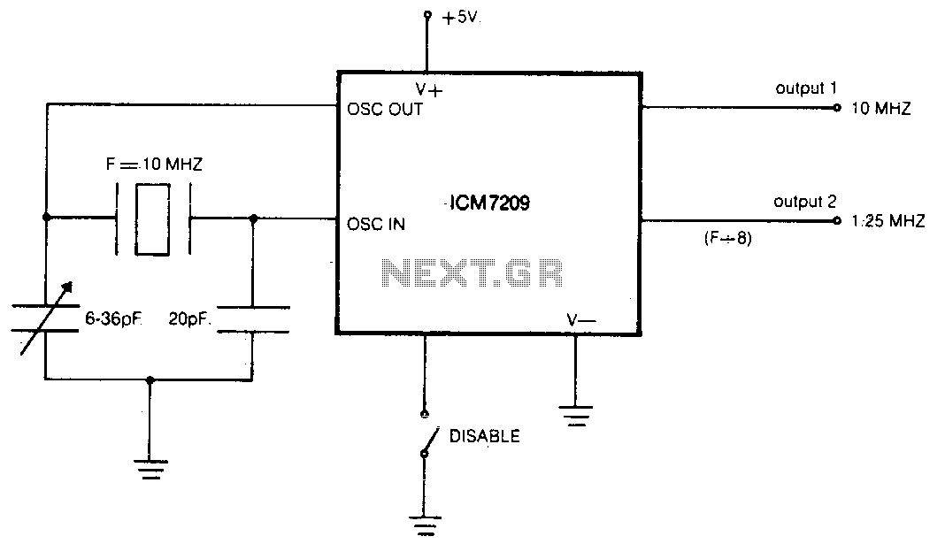
The CMOS IC directly drives five TTL loads from either of two buffered outputs. The device operates at up to 10 MHz and is compatible with bipolar, MOS, and CMOS technologies. The CMOS integrated circuit (IC) is designed to interface...

The device utilizes the USB boot HID keyboard protocol. When connected, it can detect changes in the keyboard LED states (caps lock, num lock, scroll lock), which the firmware uses to initiate new password generation (indicated by four LED...
Square wave generators are typically based on symmetrical multivibrators using bipolar transistors of the same structure, along with two frequency-determining networks. However, a simpler oscillator can be constructed with two transistors of different structures (refer to figure 1) utilizing...