
1kHz signal generator circuit diagram

This circuit employs a 1 kHz signal generator that is essential for diagnostic and maintenance applications in various audio and communication devices. The three selectable output levels allow for flexibility in testing different equipment sensitivities. The choice of components is critical for ensuring the reliability and accuracy of the generated signal.
The resistors (RJ-0.125) are selected for their stability and precision, which is vital in maintaining the integrity of the signal. The capacitors (CBM and CDX) are chosen based on their capacitance values and voltage ratings to ensure they can handle the necessary frequencies without distortion or loss of signal quality. The switches (KNX and JT360) provide user-friendly control over the circuit's functions, allowing for easy selection of output levels.
The transformers (T1 and T2) are designed to efficiently couple the generated signal to the output while minimizing losses. The use of MTT25 ferrite pots enhances the magnetic properties, allowing for better performance at the specified frequency. The winding configurations for both transformers are meticulously calculated to achieve the desired inductance and impedance matching, ensuring optimal signal transfer.
Overall, this circuit represents a robust solution for testing and diagnosing low-frequency amplifier circuits, making it an invaluable tool for technicians and engineers in the field of electronics.This circuit can generate a signal lkHz and three output level options. It can be used to test communication equipment maintenance and barriers, can be quickly and accurately find the point of failure televisions, stereos, radios, and other low-frequency amplifier circuit. Therefore, it is an electronic device ideal signal source.Component selection: resistance using RJ-0.125, capacitors using CBM, electrolytic capacitors using CDX, switch Sl: KNX (2 1), S2: JT360 (small pull key). Transformers Tl, T2: using MTT25 ferrite pot, Tl of L1-2 with µ0.09mm high strength wire, wound 1540 turns, L3-4 with the 0.09mm high strength wire, wound 150 turns, L5-6 µ0.09mm with high strength wire, wound 330 turns; T2 of L1-2 with µ0.09mm high strength wire, wound 1528 turns, L3-4 with µ0.09mm high strength wire, wound 162 turns, L5-6 with wins 0.09mm high strength wire, wound 540 turns.
Related Circuits
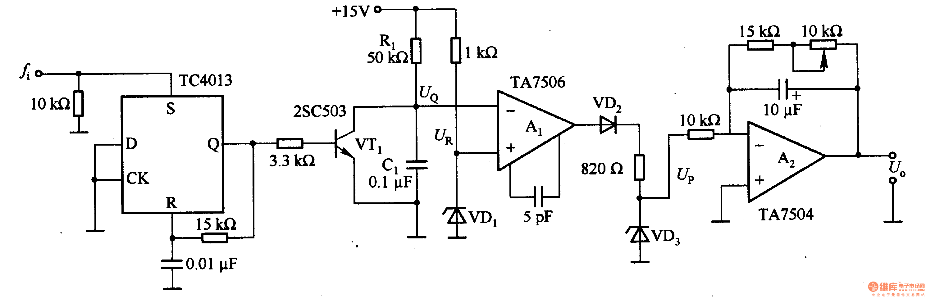
This circuit can convert an input frequency ranging from 0 to 100 Hz into an output voltage of 0 to 10 V. It utilizes the TC4013 monostable multivibrator to shape and amplify the input pulse, which has a width...
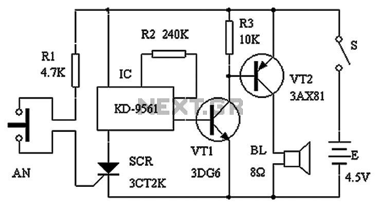
The circuit schematic presented in Figure 1 consists of an SCR, R1, and an AN SCR trigger switch circuit, along with an analog circuit composed of IC1, R2, VT1, VT2, and a BL siren. Typically, the circuit is designed...
This decibel meter circuit responds to sound pressure levels ranging from approximately 60 to 70 dB (decibels). The sound is captured by an 8-ohm speaker and amplified using a transistor stage along with an LM324 operational amplifier section. A...
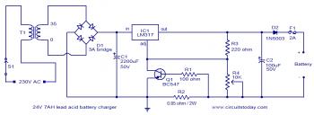
To set up the charging voltage, power on the charger and connect a voltmeter across the output terminals. Adjust R4 until the voltmeter reads 28V. The charger is now ready for battery connection. The charging circuit described involves a voltage...
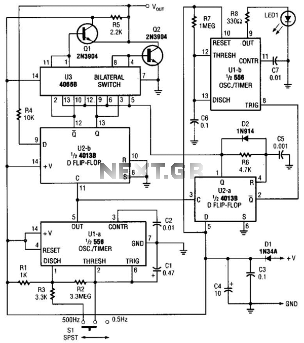
The logic pulser generates pulses at 500 Hz or 0.5 Hz. When the pulser's tip connects to an input that is already being driven high or low, the pulser senses the logic state and automatically pulses the input briefly...
The completed board may be driven by voltages between 0.8 and 3 Volts. While the basic design goal was candle-like light from a single cell, the values used were chosen to allow safe operation from 3 Volts so you...