
High-Voltage Generator with HEX FET
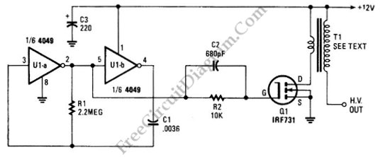
The high voltage generator circuit is designed to convert a low voltage input into a significantly higher voltage output, suitable for applications such as igniting gas burners or providing spark for ignition systems. The core component of this circuit is the 4049 hex inverter, which is a CMOS device capable of functioning as an oscillator.
In this configuration, the 4049 is connected in a feedback loop that allows it to oscillate. The oscillation frequency can be adjusted by varying the values of external resistors and capacitors connected to the inverter. Typically, a resistor-capacitor (RC) network is used to determine the timing characteristics of the oscillation. The output of the inverter can drive a transformer, which steps up the voltage to the desired level.
The circuit may also include additional components such as diodes for rectification, capacitors for filtering, and possibly a transistor for driving the transformer more effectively. The transformer is crucial as it increases the voltage generated by the oscillator to a level suitable for ignition.
Safety precautions should be considered when working with high voltage circuits, including proper insulation and handling procedures to prevent electric shock. Additionally, the circuit should be housed in a suitable enclosure to protect users from accidental contact with high voltage components.
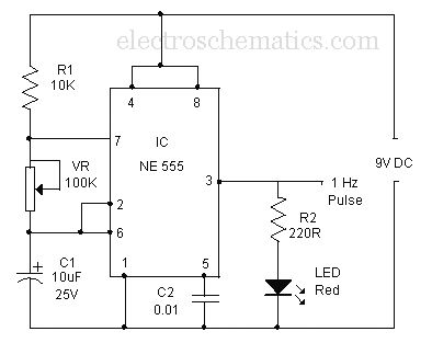
Overall, this high voltage generator circuit is a practical solution for applications requiring a reliable ignition source, with the 4049 hex inverter serving as a versatile and efficient oscillator.The schematic diagram below show a circuit of high voltage generator. This circuit uses a 4049 hex inverter as an oscillator, and you can use ignition. 🔗 External reference
Related Circuits
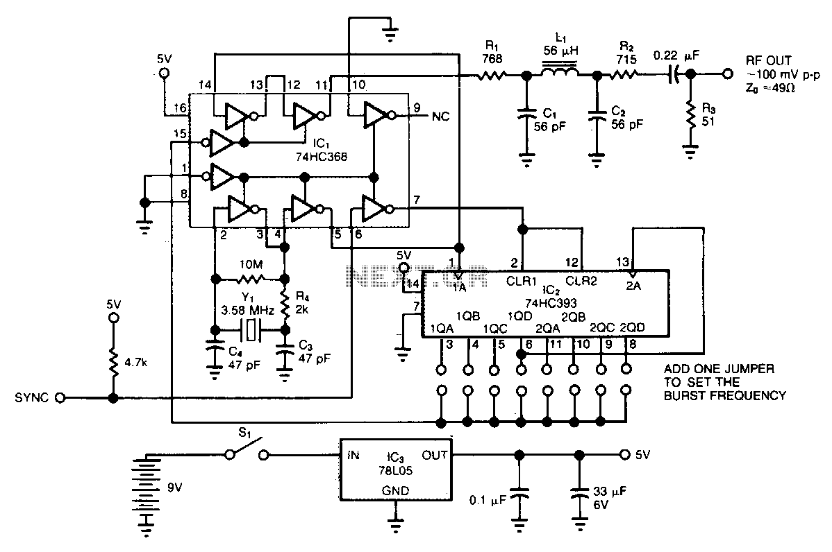
The circuit generates low-level RF bursts with frequencies up to 10 MHz, allowing for field testing of high-frequency receivers. A jumper-selectable binary fraction (1/2 to 1/256) of the Y1 crystal frequency gates the output RF signal. The output amplitude...
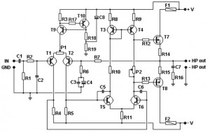
This basic MOSFET amplifier is simple to construct and low-cost, making it ideal for Hi-Fi amplifiers and instrument amplifiers such as guitars and keyboards. It delivers an output power of ±100 W RMS at an 8-ohm load or ±160...
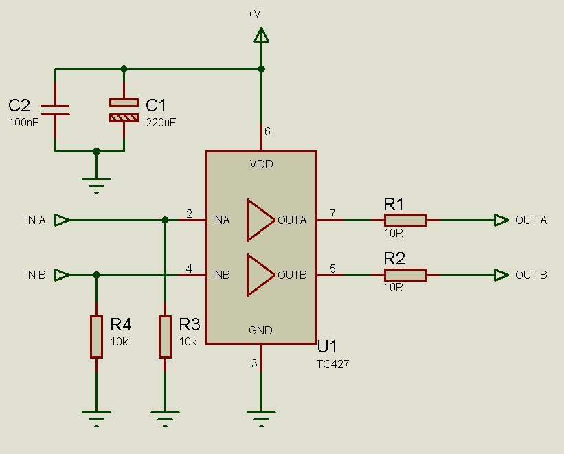
MOSFETs cannot simply be connected to the drive signal and expected to function correctly. Due to their construction, driving MOSFETs can be complex, particularly for beginners. Many users frequently seek assistance with MOSFET drive issues on various blogs, websites,...
A simple triangle and square wave generator utilizing a common 1458 dual op-amp, capable of operating from very low frequencies up to approximately 10 kHz. The time interval for one half-cycle is determined by the product of resistance (R)...
This application note describes the implementation of a single-supply triangular wave oscillator using the MAX9000 integrated circuit and several passive components. The circuit employs an operational amplifier, a comparator, and a voltage reference as the main active components. The...
A simple buzzer is being converted into an oscillating buzzer to produce a sound similar to that of an automobile's reverse indicator. The schematic provided is borrowed from electroschematics.com. The intention is to replace the LED in the circuit...