
10 band graphic equalizer schematic
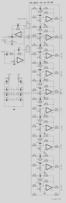
The circuit design features ten filter units, each tailored to operate within specific frequency bands dictated by the capacitance values of their capacitors. This configuration allows for precise tuning of audio signals across a range of frequencies, enhancing the overall sound quality. The use of potentiometers enables users to fine-tune the frequency response, allowing for customization based on individual preferences or specific audio requirements.
In stereo applications, the circuit is split into two identical sections, ensuring that both channels maintain a consistent frequency response. This design consideration is crucial for achieving a balanced audio output, preventing discrepancies that could arise from variations in component values or characteristics between the two channels.
The inclusion of switch S1 adds versatility to the circuit. When engaged, it isolates the equalizer circuit from the audio path, allowing for a direct signal flow that maintains a flat frequency response. This feature is particularly useful when the equalization is not desired, ensuring that the audio output remains unaltered during playback.
The overall circuit is designed to be integrated between a preamplifier and a final power amplifier. This positioning is strategic, as it allows the equalization process to occur before amplification, ensuring that the audio signal is optimally shaped before being sent to the power amplifier for driving speakers. Properly implementing this circuit can significantly enhance audio performance, providing users with the flexibility to tailor their listening experience.As shown in the diagram, there are 10 same units that only differ in capacitance values of capacitors which determine the frequency band of each filter. The potentiometers adjust the predetermined regions of frequency in each unit. If it is intended for stereo use then it will be supposed it is made in two pieces with as much as possible suited th
e materials, between the channels, so that do not exist differences in the regulation of each band frequencies. Switch S1 isolates the circuit EQ, when him we did not need and it ensures level [ flat ] response in the exit of circuit.
The circuit should be connected between preamplifier and in a final power amplifier. 🔗 External reference
Related Circuits
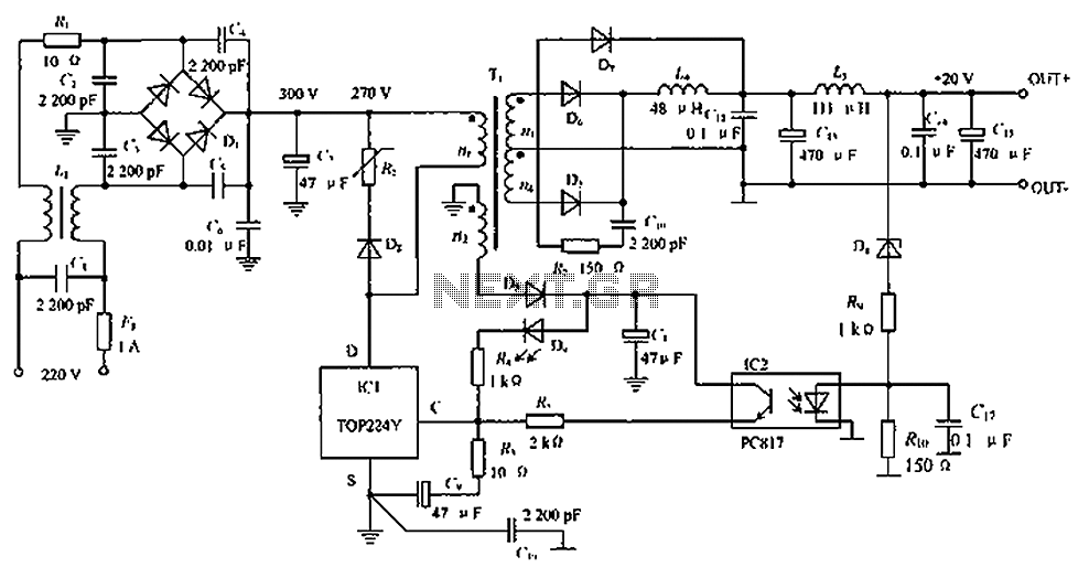
The circuit depicted in the figure is designed to achieve a higher power output by modifying specific components. On the left side of the figure, components R1, L1, D1, and capacitors C1 to C7 form a conventional filtering and...
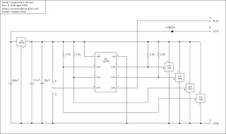
The microcontroller program is designed to support two communication protocols: the one-wire bus utilized by the DS1820 temperature sensor and the serial protocol used for communication with a computer. Upon power-up, the program retrieves data from the temperature sensors...
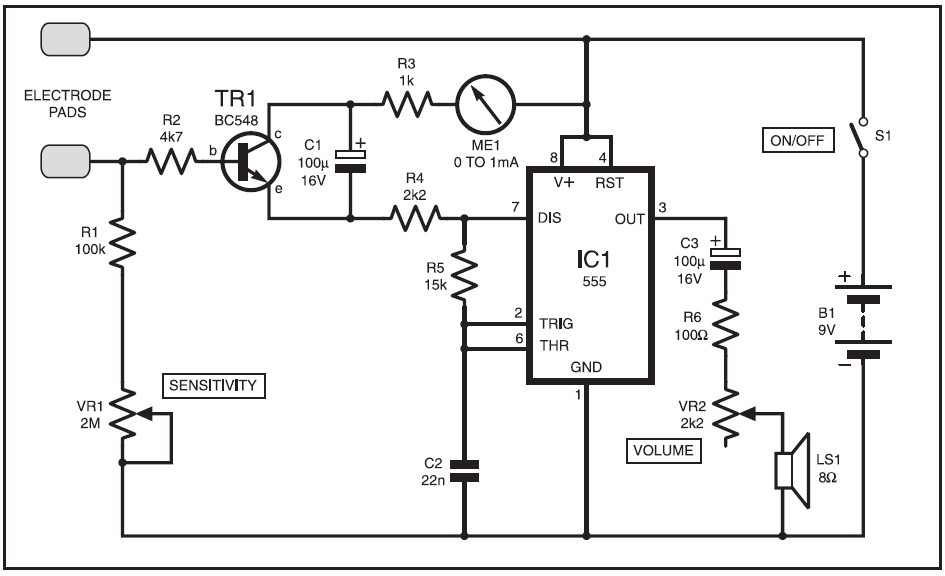
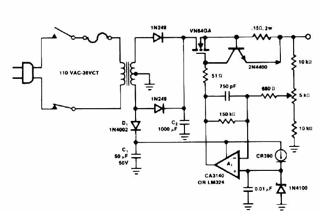
This instrument is designed to help relieve nervous tension for individuals returning home from work with lingering stress. Known as the Galvanic Skin Response Monitor, it operates based on changes in skin resistance that correlate with emotional states. Increased...
This circuit outputs a voltage of 14 volts with a maximum current of 4A. It can be used for NiCad batteries and accumulators, both wet and dry types. However, the accumulator must be rated for 12 volts and have...
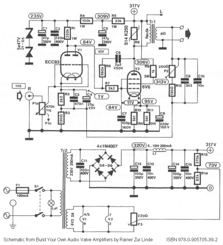
Direct-coupled single-ended (SE) 6V6 and 6V6GT tube amplifier schematic with ECC83 driver stage. From the book "Build Your Own Audio Valve Amplifier" by Rainer zur Linde. The described circuit represents a direct-coupled single-ended tube amplifier utilizing 6V6 or 6V6GT vacuum...
This circuit is used to slowly illuminate and fade a pair of red LEDs (light emitting diodes). The fading LEDs could be installed as 'eyes' in a small pumpkin or skull as a Halloween attraction, or mounted in a...