
10 Mhz QRSS Beacon
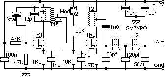
The described beacon circuit employs a Colpitts oscillator configuration, which is known for its stability and simplicity in generating RF signals. The oscillator is tuned to the QRSS frequency of 10140.020 kHz using a quartz crystal, which ensures precise frequency control. The inclusion of a 2N2222A transistor in the power stage allows for efficient amplification of the RF signal, achieving the desired output power of 20 milliwatts.
For filtering, the absence of a low-pass filter in the initial tests indicates a focus on basic functionality, with the Kenwood Antenna Tuner acting as an alternative to manage unwanted harmonics and provide a cleaner output signal. This approach is practical for early-stage testing, allowing for quick adjustments and monitoring of the signal quality.
The NE555 timer circuit serves as a versatile component in this design, generating a pattern for the CW keying. By modulating the output of the oscillator, it produces Morse code signals that can be visually monitored on the ARGO software, which is commonly used for decoding and analyzing weak signals in the QRSS spectrum.
Overall, this beacon design represents a blend of various inspirations and practical engineering choices, showcasing an effective method for amateur radio experimentation in the QRSS domain. The use of readily available components and simple circuitry makes it accessible for hobbyists while providing a platform for further enhancements and refinements in future iterations.My beacon is using now a simple CW keying QRSS3 10140. 020 khz, power is 20 milliwatt. I`m using a PIC program PicBeacon di Ik2pcb. Click here for the reception report The idea of making this beacon start from two project, one is the Hans G0GPL QRSS Junkbox Beacon and the other is the simple "2 transistor" project from Colin G6AVK. Using this two circuit and also looking idea from Alessandro I0SKK Beacon i start the builing with ugly construction (or ground-plane construction) my beacon. Using a simple 10140 khz xtal (Tnx Peter DL6NL !)i build the Colpitts oscillator and the "power" stage with a 2n2222a transistor.
In the first test the "low pass" filter is not used as you can see in the photo, as a "band filter" i`m using Kenwood Antenna Tuner. A simple circuit with NE555 is used as a patten generator, and in the ARGO screen look like a lot of "T" in morse Code.
The frequency is 10140. 020 Khz. 🔗 External reference
Related Circuits
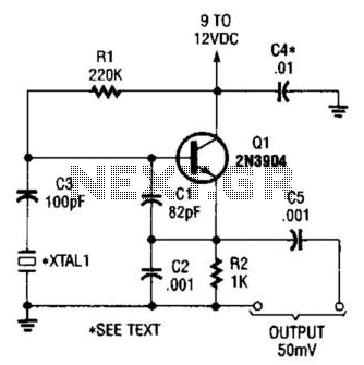
This is a simple Colpitts crystal oscillator for 1 to 20 MHz, which can be easily constructed from spare parts, provided that a crystal is available. The Colpitts oscillator is a type of electronic oscillator that utilizes a combination of...
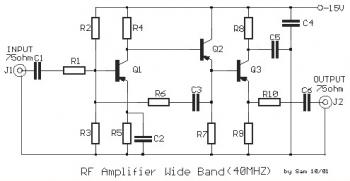
This is a 40 MHz RF amplifier circuit. The sensitivity of a receiver can be significantly enhanced by integrating this circuit between the receiver and the antenna. The amplifier does not utilize resonant circuits and is suitable for both...
An active antenna operating within the frequency range of 100 kHz to 30 MHz, characterized by its compact size and effective performance. It is designed to be simple and low-cost, making it ideal for remote medium wave and short-wave...
The 10-meter 27MHz continuous wave (CW) radio amplifier is equipped with the VN66AF transistor produced by Siliconix, which offers several advantages: it is inexpensive, provides excellent dielectric insulation, and has high gain. The VN66AF is utilized as an RF...
The original TX was designed to be only PULSE Modulated for a proportional R/C system, but I later used the same circuit to make an HF bands Amplitude Modulation (AM) transmitter using PA-Base Modulation. It eliminated the need for...
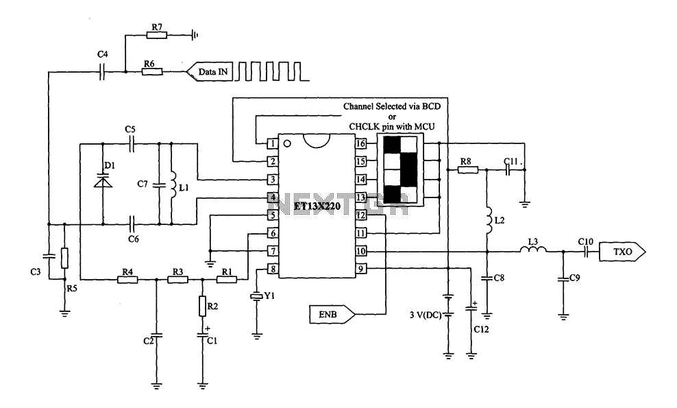
The ETl3X220 is connected to a low-cost single-chip RF transmitter, capable of supporting 10 communication channels for wireless mouse, keyboard, and other communication products. The main technical features include analog FM or digital FSK modulation with a channel spacing...