
27MHz CB Amplifier Circuit
The 10-meter 27MHz CW radio amplifier circuit utilizes the VN66AF transistor, which is a vertical N-channel MOSFET designed for efficient RF applications. The transistor's high gain characteristics make it suitable for amplifying weak radio signals in the 26-30 MHz frequency range, which is critical for effective communication in amateur radio.
The circuit design incorporates a biasing network to ensure the VN66AF operates in its optimal region, allowing for linear amplification when required. For applications involving AM and SSB, the gate current must be precisely set to 20mA. This is achieved through the adjustment of potentiometer P1, which allows for fine-tuning of the gate voltage, ensuring the transistor remains in the active region for linear amplification.
When configuring the amplifier for FM and CW modes, it is essential to adjust P1 to eliminate any gate current. This adjustment is crucial as it prevents distortion and ensures that the amplifier operates efficiently in these modes. The steady-state current, which is the current flowing through the transistor when it is in operation, is maintained between 200mA and 300mA. This range is critical for achieving the desired output power while preventing overheating and ensuring reliability.
The circuit should also include appropriate bypass capacitors to filter out noise and stabilize the power supply. Additionally, an output matching network may be necessary to ensure maximum power transfer to the antenna, optimizing the amplifier's performance. Proper heat sinking should be employed to dissipate heat generated by the VN66AF during operation, safeguarding the transistor from thermal damage.
In summary, the 10-meter 27MHz CW radio amplifier utilizing the VN66AF transistor is an effective solution for amateur radio applications, offering flexibility for various modulation types while ensuring reliable performance through careful biasing and current management.The 10 meters 27MHz CW radio amplifier is equiped with VN66AF transistor produced by Siliconix wich has some advantages: its cheap, great dielectric insulation and high gain. Here we use VN66AF as an rf amplifier for 10m band (26 30 MHz ). For linear applications (AM and BLU) the VMOS FET gate current has to be 20mA adjusted with P1. If we wan t to use this 10m rf amplifier for FM and CW adjust P1 so there is no current to FET gate. In our case the repose current ( steady current ) is 200mA to 300mA. 🔗 External reference
Related Circuits
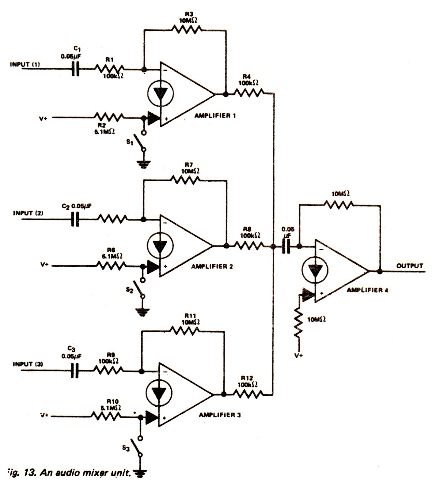
The amplifiers of an LM3900N device can be utilized to create an audio mixer unit that allows for the combination of three separate audio signals into a single composite output. The audio mixer circuit provided operates with a single...

This automatic light dimmer circuit enables controlled lighting that gradually turns on or off. The operation is as follows: when switch S1 is closed, capacitor C1 charges slowly. Once the voltage across C1 reaches 0.6 volts, transistor T1 begins...
The distortion produced by a typical solid-state Class-B power amplifier consists of eight mechanisms, all of which may coexist and whose distortion products overlap to create a complex result. Methods for isolating each mechanism for study and minimizing its...
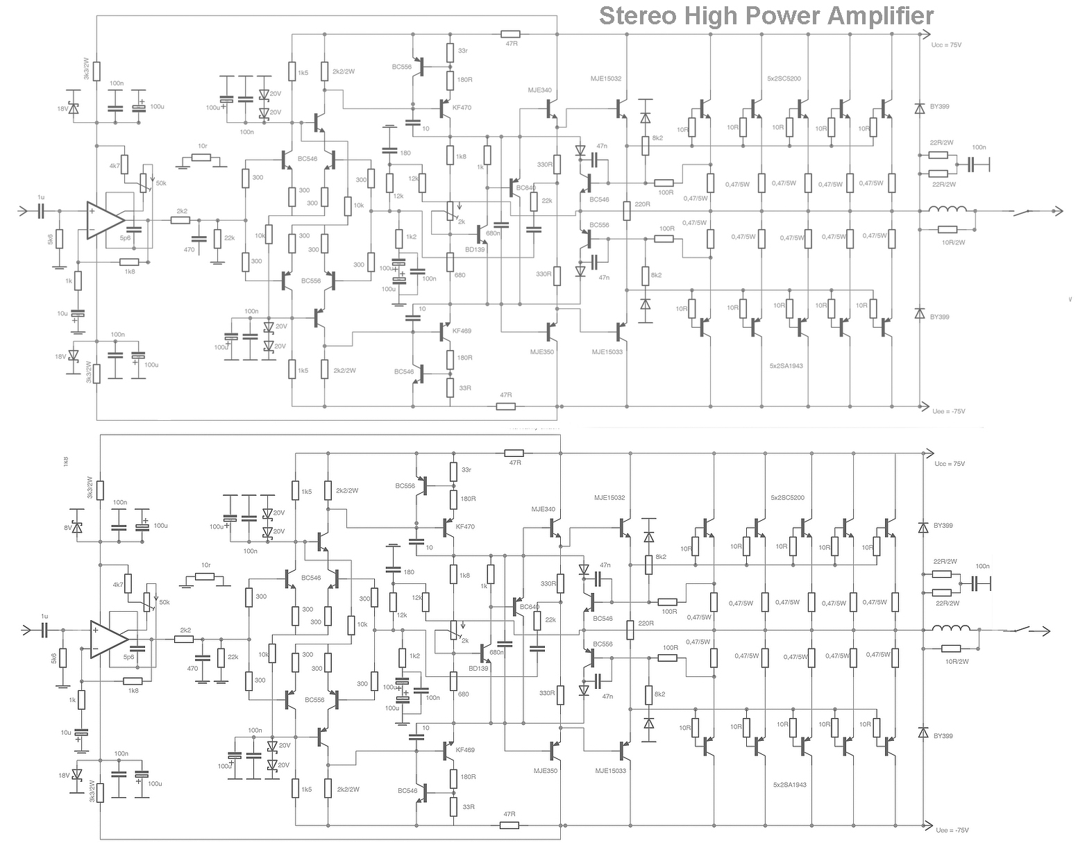
This is a stereo amplifier circuit that delivers high output power and excellent sound quality. The amplifier circuit features a very high gain output stage, which can result in signal noise deterioration. It is capable of providing an output...
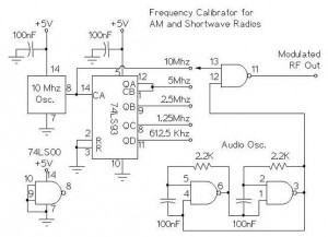
The following circuit illustrates an AM/Shortwave Radio Frequency Calibrator Circuit Diagram. This circuit is based on the 74LS93 IC. Features: The .. The AM/Shortwave Radio Frequency Calibrator Circuit utilizes the 74LS93 integrated circuit, which is a 4-bit binary counter. This...
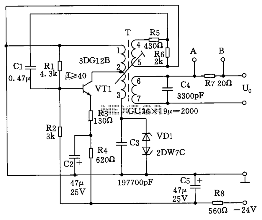
The circuit depicted in the figure allows for the selection of optimal operating conditions and a suitable allocation of the temperature coefficient for the resonant circuit components. The resonance occurs at both ends of the circuit. Additionally, the exchange...