
10 Note Sound Synthesizer Circuit
IC2, another 555 timer, generates the tone, with the overall pitch of the tone adjustable through potentiometer P2. As the outputs from the 4017 sequence, the tone frequency changes with each output shift and is directed to a small speaker from pin 3 of IC2. An LED, which blinks with each clock pulse, is connected to pin 3 of IC1. Switch S2 is implemented to toggle between flowing and distinct notes.
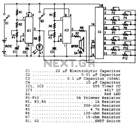
The circuit features a sound generation system utilizing three integrated circuits: two 555 timers (IC1 and IC2) and a 4017 Johnson counter (IC3). IC1, configured as an astable multivibrator, generates a continuous series of clock pulses whose frequency is adjustable through the trimmer potentiometer P1. The output from IC1 drives the clock input of IC3, which sequentially activates its output pins with each incoming clock pulse. This sequential output allows for the generation of distinct musical notes.
The trimmer resistors connected to each output pin of IC3 allow for fine-tuning of the frequency for each note produced. These resistors are linked to pin 5 of IC2, which serves as the control voltage input. By adjusting these trimmers, the pitch of the notes can be modified, enabling a range of sound variations.
IC2 takes the clock pulses received from IC3 and converts them into audible tones, with the pitch regulated by the second trimmer potentiometer, P2. The output from IC2 is fed to a small speaker connected to pin 3, producing sound that corresponds to the active output of IC3. The LED connected to pin 3 of IC1 serves as a visual indicator, flashing in sync with the clock pulses, enhancing the circuit's functionality.
Additionally, switch S2 allows the user to toggle between different sound modes, providing options for flowing notes or distinct, separated tones. This feature enhances the versatility of the circuit, making it suitable for various applications, including sound effects or musical instruments. Overall, this design showcases a straightforward yet effective method of sound generation through the interaction of timer and counter ICs. As shown, three ICs are used to produce the sounds. ICl is a 555 timer that generates clock pulses. It is configured as an astable multivibrator. The frequency of the clock pulses is set by trim: mer potentiometer PI. These clock pulses are coupled to the input of IC3 (a 4017 CMOS Johnson counter) on its clock input pin 14. Each clock pulse causes IC3 to shift a high to each of its output pins in sequence. A trimmer resistor, which can be adjusted to set a different frequency for each note, is connected to each of IC3`s output pins.
One side of each of the trimmers is connected to pin 5 (the control voltage pin) of IC2. IC2, another 555 timer IC, creates the tone; the overall pitch of the tone can be varied by P2. As the output sequences from the 4017, that tone, which is changed in frequency by each output shift is applied to a small speaker from pin 3 of IC2. An LED, which flashes with each clock pulse, is connected to pin 3 of ICl. Switch S2 is used to vary the sound between flowing and distinct notes. 🔗 External reference
Related Circuits
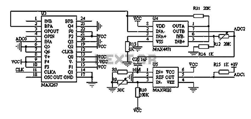
The filtering and amplifying circuit consists of two main components. The MAXIM MAX267 filter is an integrated circuit that can function as a low-pass, band-pass, high-pass filter, and other configurations, offering superior performance compared to traditional op-amp filters. The...

The circuit operation principle of the device illustrated in the figure is as follows: When the barbed wire is intact, the output pin of the LSE is high due to the absence of contact. Consequently, the transistor VT is...
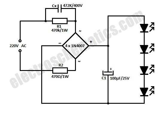
This is a simplified version of a white LED lamp that can be powered directly from the mains. It provides sufficient illumination for reading purposes. Capacitor Cx along... The circuit for the white LED lamp consists of several key components...
This is a true subwoofer circuit designed specifically for 15- to 18-inch woofers and is not compatible with 6- or 8-inch subwoofers. It features a bass-reflex design. The true subwoofer circuit operates by utilizing a bass-reflex enclosure, which enhances low-frequency...
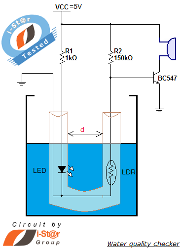
How to measure water purity and test water quality using a simple electronics project. Water purity measurement and water quality analysis can be performed using a water purity checker circuit. This circuit is constructed around a Light Dependent Resistor...
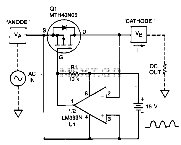
A TMOS power FET, Q1, and an LM393 comparator provide a high-efficiency rectifier circuit. When voltage V1 exceeds V2, the output of U1 becomes high, and Q1 conducts. Conversely, when V2 exceeds V1, the comparator output becomes low, and...
Warning: include(partials/cookie-banner.php): Failed to open stream: Permission denied in /var/www/html/nextgr/view-circuit.php on line 713
Warning: include(): Failed opening 'partials/cookie-banner.php' for inclusion (include_path='.:/usr/share/php') in /var/www/html/nextgr/view-circuit.php on line 713