
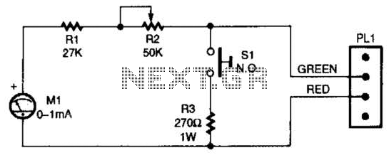
Water quality checker project simple circuit diagram
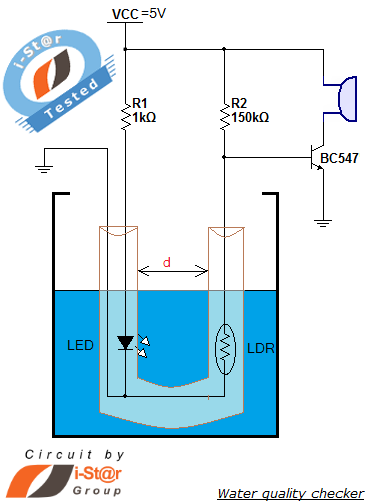
The water purity checker circuit utilizes an LDR, which changes its resistance based on the light intensity that passes through the water. When water is clear, more light reaches the LDR, resulting in lower resistance. Conversely, as the water becomes increasingly contaminated, the turbidity increases, reducing the amount of light that reaches the LDR and causing its resistance to rise. This change in resistance can be converted into a voltage signal using a voltage divider circuit, which can then be monitored by a microcontroller or a simple comparator circuit.
To implement this project, the circuit typically includes a power supply, the LDR, a resistor for the voltage divider, a comparator (such as an operational amplifier), and a piezo buzzer for the alert sound. The comparator is set up to trigger when the voltage from the LDR exceeds a predetermined threshold, indicating poor water quality. When this condition is met, the comparator output activates the piezo buzzer, providing an audible alert.
For practical applications, the circuit can be housed in a waterproof enclosure to ensure durability and reliability in a wet environment. Calibration may be necessary to adjust the threshold according to specific water quality standards. The integration with a water tank level controller can enhance the functionality, allowing for simultaneous monitoring of both water purity and level, making it a comprehensive solution for water management in domestic settings. This project not only serves as a useful tool for ensuring water quality but also provides an educational opportunity for understanding basic electronics and environmental monitoring.How to measure water purity How to test water quality using a simple electronics project You can perform water purity measurement and water quality analysis using this water purity checker circuit. This circuit is built around a simple LDR (Light Depended Resistor) and some discrete components. The most attractive feature of our water purity tes ter is that it gives a beep sound when the water purity level goes below a threshold value. You can implement this simple electronic project in your domestic water tank for water quality monitoring and testing. The detailed circuit diagram and constructional details of water quality testing device are given in this article.
Also you can integrate this with our previous circuit of water tank level controller, the resulting circuit will be an advanced engineering project. When the amount of mud in the water reservoir exceeds a threshold value, our water quality testing equipment starts producing a beep sound to alert us that the quantity of mud in the water has increased and needs a cleaning.
🔗 External reference
Related Circuits
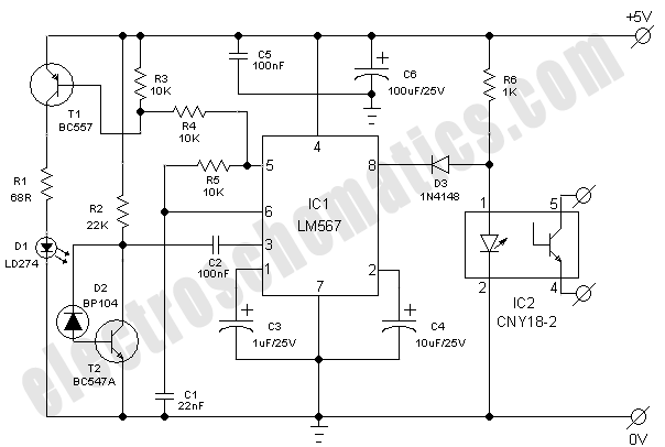
This simple and economical infrared model train detector circuit is designed specifically for hobbyists who want to incorporate a smart sensor to detect trains on their model railway track. The schematic diagram illustrates a straightforward configuration comprising an infrared...
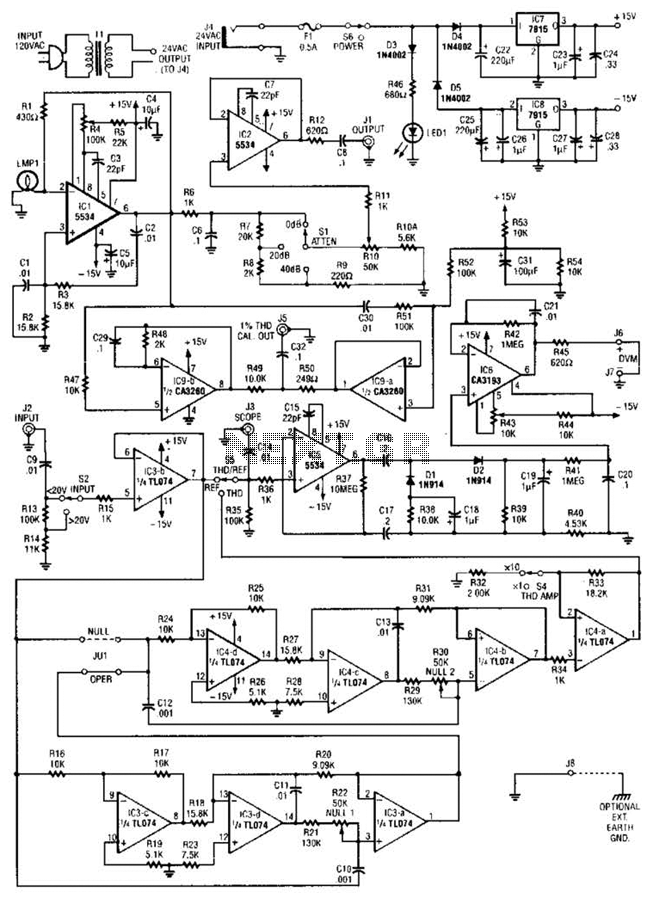
The circuit comprises a low-distortion, 1-kHz oscillator designed to measure Total Harmonic Distortion (THD) at a user-selected voltage level, suitable for voltage amplifiers or for testing amplifiers with power levels up to 600 W. It is capable of detecting...
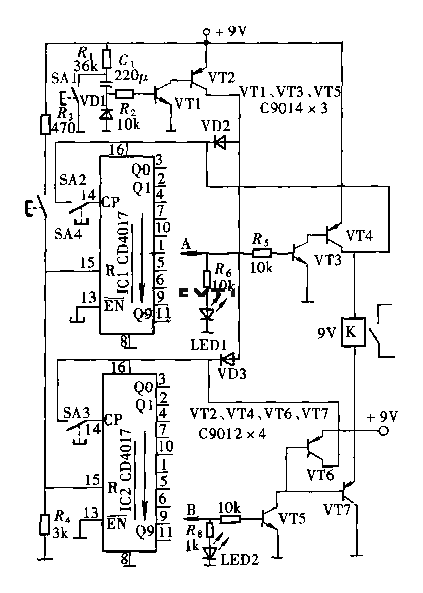
The circuit consists of a two and four decimal counter CD4017 used in conjunction with a password switch. It is composed of the output terminals from the key switch logic combination of components, which provide another feature of the...
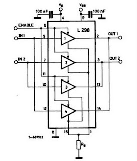
The IC H-Bridge DC motor driver L298 contains two H-Bridge circuits, allowing it to drive two DC motors simultaneously. Each H-Bridge circuit can deliver currents up to 2A. When used in parallel, the L298 can provide a total current...
This is an enhanced infrared (IR) remote control extender circuit that exhibits high noise immunity, resistance to ambient and reflected light, and an extended operational range of approximately 7 meters between the remote control and the extender circuit. It...
When the switch SI is pressed, the silicon-controlled rectifier (SCR) is activated, connecting LED1 and resistor R1 across the telephone line. This action causes the line voltage to drop to approximately 20 volts, which maintains the connection to the...