
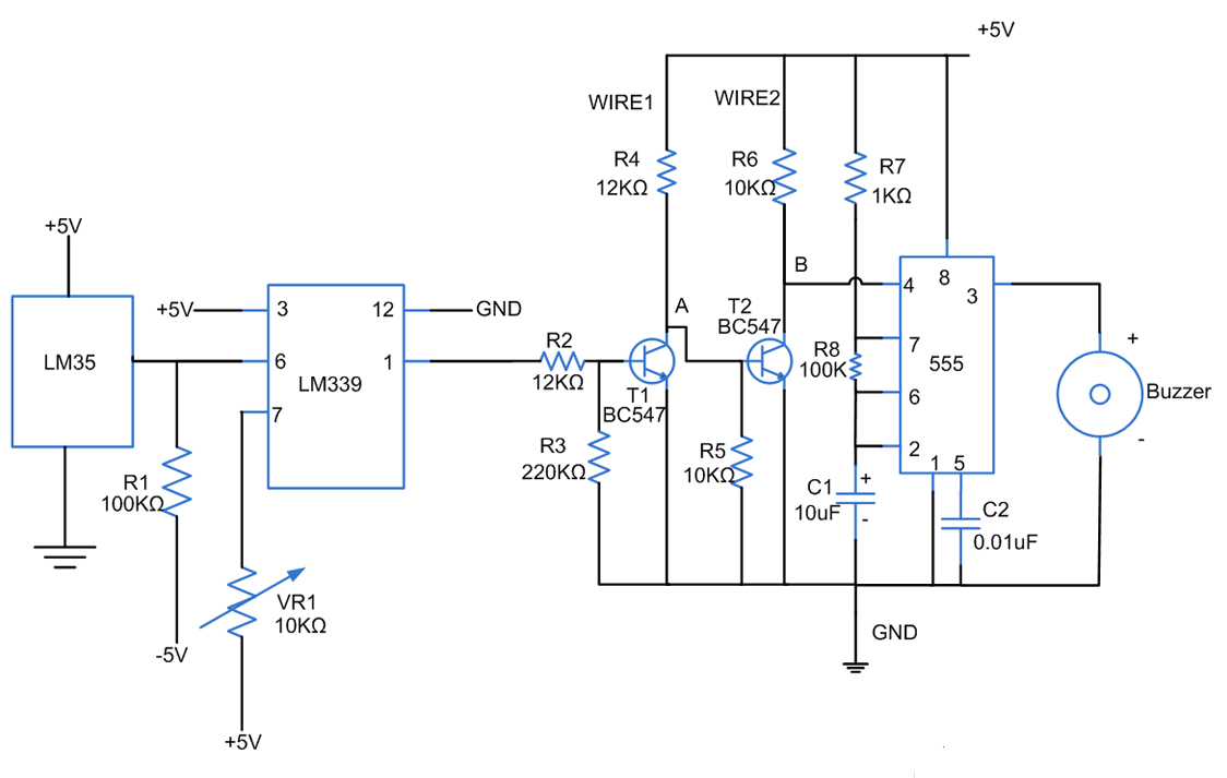
Low pressure break alarm circuit diagram

The described circuit operates based on the integrity of a barbed wire sensor, which serves as a security mechanism. When the barbed wire remains undisturbed, it creates a high signal at the output pin of the LSE (Line Sensor Element). This high signal indicates that there is no breach in the monitored area, maintaining the system in a standby state.
In the circuit, the transistor VT acts as a switch that controls the relay J. When the output from the LSE is high, the base of the transistor is not sufficiently energized, leading to its non-conduction state. Consequently, the relay J, which is responsible for activating the alarm system, remains deactivated.
In the event of a disturbance to the barbed wire, the output from the LSE will drop to a low state. This change triggers the base of the transistor VT, allowing current to flow through it and turning it on. As a result, the relay J is energized, which activates the alarm system, alerting users to a potential security breach.
The circuit can be enhanced by incorporating additional components such as a diode across the relay coil for flyback protection, ensuring that voltage spikes do not damage the transistor when the relay is switched off. Furthermore, a resistor may be added to the base of the transistor to limit the current and prevent damage to the transistor from excessive current flow.
Overall, this circuit design effectively utilizes a simple yet reliable mechanism to monitor the integrity of a security barrier, providing an essential function in security and surveillance applications.Circuit operation principle of the device shown in Figure. When the barbed wire Fe intact, LSE's O, feet collusion between its pin output high, the transistor VT end, the relay J is released, the alarm does not work.
Related Circuits
Fires can occur for several reasons, such as forgetting to turn off equipment like irons. A fire alarm circuit with a temperature sensor may be one option to secure homes from fire hazards. There are also fire alarm circuits...
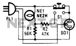
If residing in a cold climate, it is reassuring to confirm the functionality of an engine-block heater. This device indicates whether the heater is operational. To use, connect PL1 to a power outlet; the NE1 indicator should illuminate. Next,...
This is a pressure sensor signal conditioning circuit. It is a simple and inexpensive circuit due to its small geometry and the use of a straightforward pressure sensor. The pressure sensor signal conditioning circuit is designed to convert the raw...

The TPS61200 specifications indicate that GND serves as the control/logic ground, while PGND is designated as the power ground. However, this distinction is not accurately represented in the symbols used in the diagram. There is also confusion regarding the...

ECL integrated circuit non-saturated digital logic circuits. CMOS and ECL interface circuit shown in cross. ECL (Emitter Coupled Logic) integrated circuits are designed to operate in a non-saturated mode, providing high-speed digital logic functionality. These circuits are characterized by their...
This schematic has been modified from an old Bell & Howell projector amplifier for model 302, utilizing PP 6V6 tubes with a 12AU7 phase inverter (PI). The PI circuit appears to be closest to a "floating paraphase." There is...