
100Khz Crystal Calibrator

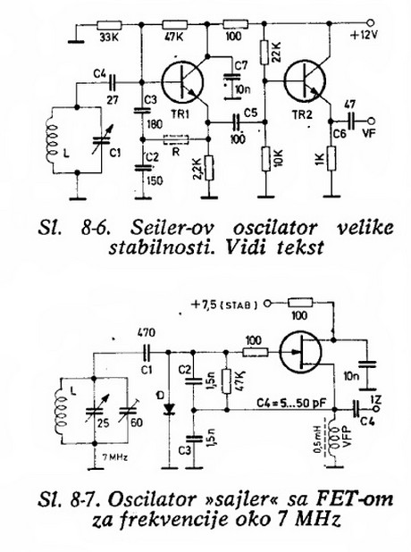
The described crystal calibrator operates on a 12-V power supply and is designed to enhance the functionality of shortwave receivers. The circuit utilizes two transistors, Q1 and Q2, which are configured to form a Colpitts oscillator. This type of oscillator is characterized by its ability to generate a stable frequency output, which is essential for tuning and calibration purposes in SW receivers.
In the oscillator configuration, Q1 and Q2 work in tandem to produce an oscillating signal. The frequency of oscillation is determined by the values of the capacitors and inductors in the circuit, specifically designed to match the desired frequency range for shortwave applications. The output from this oscillator is typically a sine wave or a square wave, depending on the specific design and components used.
Q3 serves as a buffer amplifier, isolating the oscillator from the load and ensuring that the signal is strong enough to drive subsequent stages of the SW receiver without distortion. This buffering action prevents loading effects that could otherwise alter the frequency or amplitude of the oscillating signal, maintaining the integrity of the calibration process.
The overall design emphasizes stability and precision, making it a valuable tool for radio enthusiasts and professionals who require accurate frequency calibration in their shortwave receivers. Proper selection of components, such as the crystal used for frequency stabilization and the values of passive components, is crucial for achieving optimal performance. Using a 12-V supply, this crystal calibrator should prove a useful accessory for a SW receiver. Ql and Q2 form a n oscillator and Q3 is a buffer amp.
Related Circuits
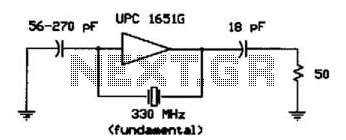
A /xPC 1651G IC operates in the fundamental mode with an experimental crystal at 330 MHz. The 56-to-270 pF capacitor is not critical; about +1 dBm RF output is available. The /xPC 1651G integrated circuit (IC) is designed to function...
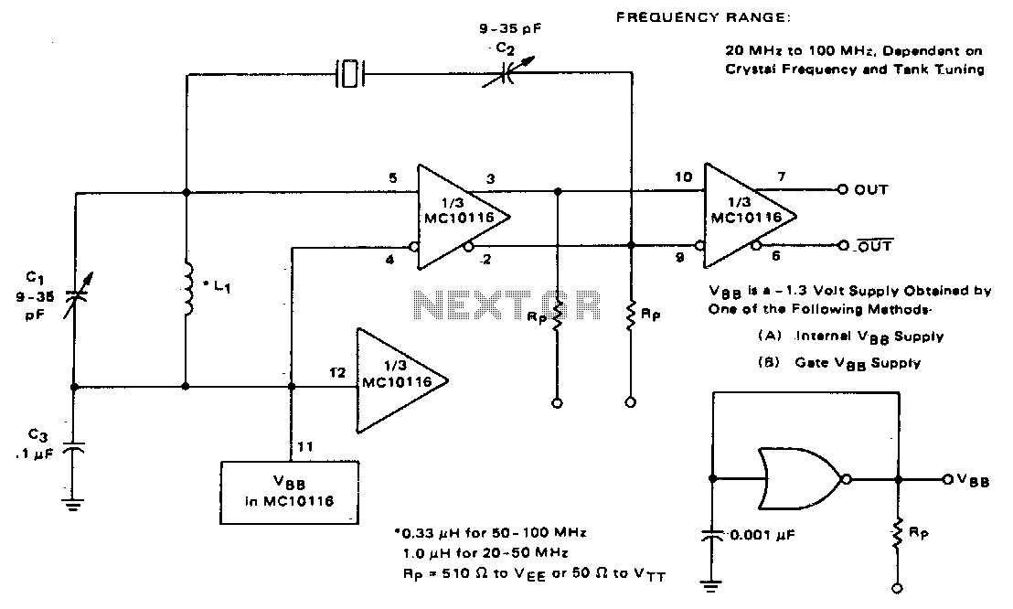
This circuit utilizes an adjustable resonant tank circuit that ensures operation at the desired crystal overtone. Capacitor C1 and inductor L1 form the resonant tank circuit, which can be adjusted to achieve a resonant frequency ranging from approximately 50...
Will an LC-based oscillator be able to demonstrate performance comparable to crystals under such conditions (possibly in unusual configurations like LC-opamp) so that any energy loss at each stage is recovered, resulting in a narrower bandwidth? Examine some amateur...
The RF engineer sometimes needs an instrument that can reliably and quickly test a low-frequency quartz crystal unit. Finding such equipment can be challenging, and engineers often refer to electronic circuit handbooks for schematics that can perform this task....
Because it uses few parts, a printed circuit board is not necessary; components can simply be soldered to one another. However, a box is desirable for operating convenience. The case and aerial from a discarded toy walkie-talkie was used...
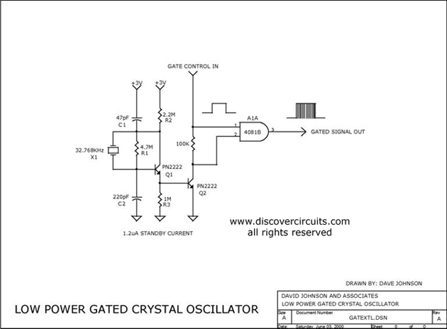
The circuit controls the output of a continuously operating 32KHz crystal oscillator, directing it to the input of a C-MOS buffer when clock pulses are required. This technique addresses the issue of a slow-starting crystal oscillator by maintaining the...