
Overtone crystal oscillator
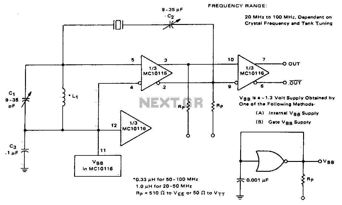
The described circuit features a resonant tank circuit composed of a capacitor (C1) and an inductor (L1), which are configured to create a tunable resonant frequency. This design is particularly advantageous for applications requiring precise frequency control, such as in radio frequency (RF) oscillators or signal generators. The adjustable nature of the tank circuit allows for fine-tuning of the resonant frequency, which is critical for achieving optimal performance across the specified frequency range of 50 MHz to 100 MHz.
In practical terms, the adjustment mechanism might involve variable components, such as a variable capacitor or an adjustable inductor, which can be tuned to achieve the desired overtone frequency. The circuit's ability to provide low impedance to off-frequency signals while presenting high impedance to the target frequency is essential for maintaining stability and ensuring that the oscillator operates effectively at the intended overtone. This impedance behavior enhances the feedback loop, allowing the oscillator to sustain oscillations at the desired frequency without interference from unwanted harmonics or noise.
Furthermore, the design of the tank circuit is crucial in determining the quality factor (Q) of the oscillator, which directly influences the bandwidth and stability of the generated signal. A higher Q factor implies a narrower bandwidth and improved selectivity, making it ideal for applications where signal integrity is paramount.
Overall, this adjustable resonant tank circuit is a vital component in achieving reliable and stable operation of crystal oscillators, ensuring that they function correctly across a range of frequencies while minimizing the impact of off-frequency disturbances.This circuit employs an adjustable resonant tank circuit which insures operation at the desired crystal overtone. Cl and LI form the resonant tank circuit, which with the values specified as a resonant frequency adjustable from approximately 50 MHz to 100 MHz.
Overtone operation is accomplished by adjusting the tank circuit frequency at or near the desired frequency The tank circuit exhibits a low impedance shunt to off-frequency oscillations and a high impedance to the desired frequency, allowing feedback from the output. Operation in this manner guarantees that the oscillator will always start at the correct overtone. 🔗 External reference
Related Circuits
A marker oscillator can be constructed using an NE555 timer to generate pulses at an audio frequency. This design facilitates the identification of signals amidst interference. The oscillator can utilize a crystal with a frequency ranging from 1 to...
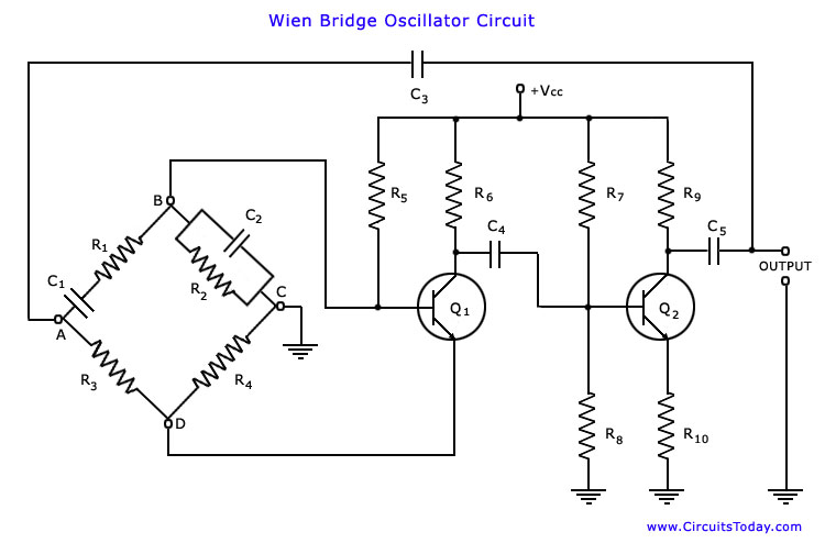
The Wien bridge oscillator is one of the most popular types of oscillators used in audio and sub-audio frequency ranges (20 Hz to 20 kHz). This oscillator features a simple design, compact size, and remarkable stability in frequency output....
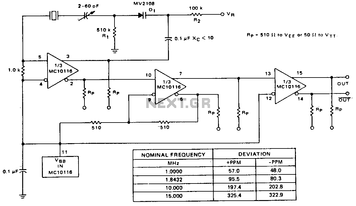
A voltage-variable capacitance tuning diode is connected in series with the crystal feedback path. Adjusting the voltage on the variable resistor (VR) changes the capacitance of the tuning diode, which in turn tunes the oscillator. The 510 kΩ resistor...
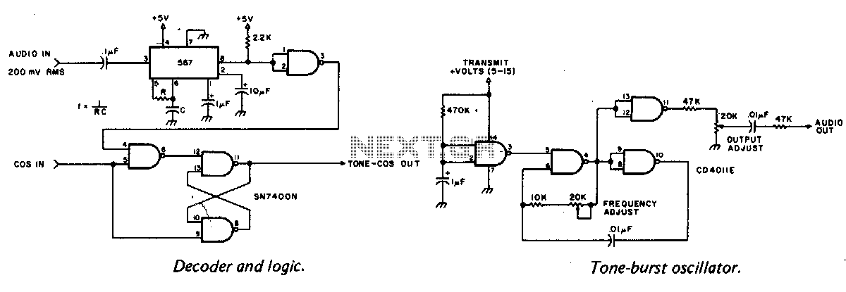
A tone burst sent at the beginning of each transmission is decoded at the receiver by a phase-locked loop (PLL), resulting in an output from pin 3 of a logic gate that activates a carrier-operated switch (COS). In this circuit,...
This oscillator utilizes a significant capacitance-to-inductance ratio. L1 is a one-turn coil made from a loop of #12 wire, measuring 12 inches in diameter. This circuit is advantageous for applications such as metal detectors, where a loop antenna is...

A high-quality QRP transmitter, named NEXUS 6, is designed to explore issues related to extremely narrow bandwidth communication. This device is not merely a simplified version of a QRP transmitter; it aims to create a cost-effective system that can...