
Field, Crystals and capacitance meters schematics
Figure One shows a schematic of an RF field strength meter. Like a crystal set, it requires no power source. However, unlike a crystal set, the meter has no tuned circuit. It responds to signals of any frequency. To test the operation of the meter, a transmitter is required to provide a source of RF. Placing the field strength meter's extended antenna near a handheld VHF rig should produce an indication on the meter, assuming that the sensitivity control has been set to maximum. No indication means that the meter is not working. Common construction errors include connecting the diodes or the meter wrongly and using silicon diodes in place of the germanium diodes specified. In this case, the meter will still work, but with reduced sensitivity. The earth wire is optional; when working with low-powered oscillators, it is useful to clip it to ground (of the circuit under test) to ensure a better indication on the meter.
Those without a transmitter can use an RF signal generator or crystal oscillator (such as that described later) for testing purposes. In this case, place the meter's antenna directly on the output terminal to verify operation. However, only attempt this with transistorised circuitry; component ratings and safety considerations make the meter described here unsuitable for poking around valve equipment. Figure Two shows the circuit of a simple crystal tester. It switches on a light emitting diode (LED) if the crystal is working.
The crystal under test is placed in an oscillator circuit. If it is working, an RF voltage will be present at the collector. This is rectified (converted to DC) and made to drive a transistor switch. Applying current to the base causes current to be drawn through the collector, thus lighting the LED.
If an indication of frequency is required, simply use a general coverage receiver to locate the crystal oscillator's output. Note however that when testing overtone crystals (mostly those above 20 MHz) the output will be on the crystal's fundamental frequency, and not the frequency marked on the crystal's case. Fundamental frequencies are approximately one-third, one-fifth or one-seventh the overtone frequency, depending on the cut of the crystal.
The circuit may be built on a small piece of matrix board and housed in a plastic box. Alternatively, a case made from scrap printed circuit board material may be used. Either a selection of crystal sockets or two leads with crocodile clips will make it easier to test many crystals quickly. The RF choke is ten turns of very thin insulated wire (such as from receiver IF transformers) passed through a cylindrical ferrite bead. Its value does not seem to be particularly critical, and a commercially-available choke could probably be substituted.
The circuit can be tested by connecting a crystal known to work, and checking for any indication on the LED. A shortwave transistor radio tuned near the crystal's fundamental frequency can be used to verify the oscillator stage's operation. Note however that this circuit may be unreliable for crystals under 3 MHz, and some experimentation with oscillator component values may be required. This project is more complex than the others described earlier. However, when finished, you will have an instrument capable of measuring all but the largest capacitors used in radio circuits. Unlike variable resistors, most variable capacitors are not marked with their values. As well, the markings of capacitors from salvaged equipment often rub off. By being able to measure these unmarked components, this project will prove useful to the constructor, vintage radio enthusiast or antenna experimenter.
The common 555 timer IC forms the heart of the circuit. Its function is to charge the unknown capacitor (Cx) to a fixed voltage. The capacitor is then discharged into the meter circuit. The meter measures the current being drawn through the 47-ohm resistor. The 555 repeats the process several times a second, so that the meter needle remains steady.
The deflection on the meter is directly proportional to the value of the unknown capacitor. This means that the scale is linear, like the voltage and current ranges on an analogue multimeter.
The meter has five ranges, from 100pF to 1uF, selected by a five-position two-pole switch. In addition, there is a x10 switch for measuring higher values and a divide-by-two facility to allow a better indication on the meter where the capacitor being measured is just above 100, 1000pF, 0.01, 0.1 or 1 uF.
Component values are critical. For best accuracy, it is desirable that the nine resistors wired to the Range switch have a 2% tolerance. If 0A47 diodes are not available, try OA91 or OA95 germanium diodes instead. Construct the meter in a plastic box; one that is about the size of your multimeter but deeper is ideal. The meter movement should be as large as the budget allows; it will be used to indicate exact values. A round 70mm-diameter movement salvaged from a piece of electronic equipment was used in the prototype. The meter will have a scale of 0 to 50 microamps. This scale needs to be converted to read 0 to 100 (i.e., 20, 40, 60, 80, 100 instead of 10, 20, 30, 40, 50). Use of white correction fluid or small pieces of paper will help here.
The components can be mounted on a piece of matrix board or printed circuit board. Use a socket for the IC should replacement ever be needed. Keep wires short to minimize stray capacitance; stray capacitance reduces accuracy.
Calibrating the completed meter can be done in conjunction with a ready-built capacitance meter. Failing this, a selection of capacitors of known value, as measured on a laboratory meter, could be used. If neither of these options are available, simply buy several capacitors of the same value and use the one which is nearest the average as your standard reference. Use several standards to verify accuracy on all ranges.
To calibrate, disable both the x10 and divide-by-two functions (i.e., both switches open). Then connect one of the reference capacitors and switch to an appropriate range. Vary the setting of the 47k trimpot until the meter is reading the exact value of the capacitor. Then switch in the divide-by-two function. This should change the reading on the meter. Adjust the 10k trimpot so that the needle shows exactly twice the original reading. For example, if a 0.01 uF reference was used, and the meter read 10 on the 0.1 uF range, it should now read 20. Now switch out the divide-by-two function.
The crystal checker also tests ceramic resonators. Other applications include use as a marker generator for homebrew HF receivers (use a 3.58 MHz crystal) and as a test oscillator for aligning equipment. The field strength meter is a useful instrument in its own right, but it can be made more versatile. Modifications include adding an amplifier (for greater sensitivity), including a tuned circuit (so it only detects signals in a particular band), or converting it into an RF wattmeter and dummy load. Circuits for such instruments are found in the standard handbooks. The meter works by converting any RF signal present at the antenna to a DC voltage. This voltage drives a meter movement to give an indication of relative RF. The meter includes a control to reduce its sensitivity where required.Because it uses few parts, a printed circuit board is not necessary; components can simply be soldered to one another. However, a box is desirable for operating convenience. The case and aerial from a discarded toy walkie-talkie was used in the prototype (see photograph), though any small plastic case will suffice.
The meter movement need not be large; we are only detecting the presence of RF, and not making precise measurements. A meter from an old radio or tape recorder should work fine. The diodes can be any germanium type; the actual part number is not important. Germanium diodes can be recognised by their 6mm-long clear glass case with two coloured bands towards the cathode end.
None of the component values shown are critical; a 50 percent variation would have little effect on circuit operation. A field strength meter is perhaps the simplest piece of RF test equipment that can be built. Used for checking transmitters, antenna experimentation, and testing RF oscillators, field strength meters provide an indication of the presence of RF energy. They are not frequency sensitive and are useful where indication of a change in level is more important than the actual strength of the signal indicated.
Figure One shows a schematic of an RF field strength meter. Like a crystal set, it requires no power source. However, unlike a crystal set, the meter has no tuned circuit. It responds to signals of any frequency. To test the operation of the meter, a transmitter is required to provide a source of RF. Placing the field strength meter's extended antenna near a handheld VHF rig should produce an indication on the meter, assuming that the sensitivity control has been set to maximum. No indication means that the meter is not working. Common construction errors include connecting the diodes or the meter wrongly and using silicon diodes in place of the germanium diodes specified.
In this case, the meter will still work, but with reduced sensitivity. The earth wire is optional; when working with low-powered oscillators, it is useful to clip it to ground (of the circuit under test) to ensure a better indication on the meter. Those without a transmitter can use an RF signal generator or crystal oscillator (such as that described later) for testing purposes.
In this case, place the meter's antenna directly on the output terminal to verify operation. However, only attempt this with transistorised circuitry; component ratings and safety considerations make the meter described here unsuitable for poking around valve equipment. Figure Two shows the circuit of a simple crystal tester. It switches on a light emitting diode (LED) if the crystal is working. The crystal under test is placed in an oscillator circuit. If it is working, an RF voltage will be present at the collector. This is rectified (converted to DC) and made to drive a transistor switch. Applying current to the base causes current to be drawn through the collector, thus lighting the LED.
If an indication of frequency is required, simply use a general coverage receiver to locate the crystal oscillator's output. Note however that when testing overtone crystals (mostly those above 20 MHz) the output will be on the crystal's fundamental frequency, and not the frequency marked on the crystal's case.
Fundamental frequencies are approximately one-third, one-fifth or one-seventh the overtone frequency, depending on the cut of the crystal. The circuit may be built on a small piece of matrix board and housed in a plastic box. Alternatively, a case made from scrap printed circuit board material may be used. Either a selection of crystal sockets or two leads with crocodile clips will make it easier to test many crystals quickly.
The RF choke is ten turns of very thin insulated wire (such as from receiver IF transformers) passed through a cylindrical ferrite bead. Its value does not seem to be particularly critical, and a commercially-available choke could probably be substituted.
The circuit can be tested by connecting a crystal known to work, and checking for any indcation on the LED. A shortwave transistor radio tuned near the crystal's fundamental frequency can be used to verify the oscillator stage's operation.
Note however that this circuit may be unreliable for crystals under 3 MHz, and some experimentation with oscillator component values may be required. This project is more complex than the others described earlier. However, when finished, you will have an instrument capable of measuring all but the largest capacitors used in radio circuits.
Unlike variable resistors, most variable capacitors are not marked with their values. As well, the markings of capacitors from salvaged equipment often rub off. By being able to measure these unmarked components, this project will prove useful to the constructor, vintage radio enthusiast or antenna experimenter. The common 555 timer IC forms the heart of the circuit (Figure Three). Its function is to charge the unknown capacitor (Cx) to a fixed voltage. The capacitor is then discharged into the meter circuit. The meter measures the current being drawn through the 47 ohm resistor. The 555 repeats the process several times a second, so that the meter needle remains steady. The deflection on the meter is directly proportional to the value of the unknown capacitor. This means that the scale is linear, like the voltage and current ranges on an analogue multimeter. The meter has five ranges, from 100pF to 1uF, selected by a five position two pole switch. In addition, there is a x10 switch for measuring higher values and a divide-by-two facility to allow a better indication on the meter where the capacitor being measured is just above 100, 1000pF, 0.01, 0.1 or 1 uF.
Component values are critical. For best accuracy, it is desirable that the nine resistors wired to the Range switch have a 2% tolerance. If 0A47 diodes are not available, try OA91 or OA95 germanium diodes instead. Construct the meter in a plastic box; one that is about the size of your multimeter but deeper is ideal.
The meter movement should as large as your budget allows; you will be using it to indicate exact values. A round 70mm-diameter movement salvaged from a piece of electronic equipment was used in the prototype.
The meter you buy will have a scale of 0 to 50 microamps. This scale needs to be converted to read 0 to 100 (ie 20, 40, 60, 80, 100 instead of 10, 20, 30, 40, 50). Use of white correction fluid or small pieces of paper will help here. The components can be mounted on a piece of matrix board or printed circuit board. Use a socket for the IC should replacement ever be needed. Keep wires short to minimise stray capacitance; stray capacitance reduces accuracy. Calibrating the completed meter can be done in conjunction with a ready-built capacitance meter. Failing this, a selection of capacitors of known value, as measured on a laboratory meter, could be used.
If neither of these options are available, simply buy several capacitors of the same value and use the one which is nearest the average as your standard reference. Use several standards to verify accuracy on all ranges. To calibrate, disable both the x10 and divide-by-two functions (ie both switches open). Then connect one of your reference capacitors and switch to an appropriate range. Vary the setting of the 47k trimpot until the meter is reading the exact value of the capacitor. Then switch in the divide-by-two function. This should change the reading on the meter. Adjust the 10k trimpot so that the needle shows exactly twice the original reading. For example, if you used a 0.01 uF reference, and the meter read 10 on the 0.1 uF range, it should now read 20.
Now switch out the divide-by-two function. The crystal checker also tests ceramic resonators. Other applications include use as a marker generator for homebrew HF receivers (use a 3.58 MHz crystal) and as a test oscillator for aligning equipment. The field strength meter is a useful instrument in its own right, but it can be made more versatile. Modifications include adding an amplifier (for greater sensitivity), including a tuned circuit (so it only detects signals in a particular band), or converting it into an RF wattmeter and dummy load.
Circuits for such instruments are found in the standard handbooks. The meter works by converting any RF signal present at the antenna to a DC voltage. This voltage drives a meter movement to give an indication of relative RF. The meter includes a control to reduce its sensitivity where required. 🔗 External reference
Related Circuits
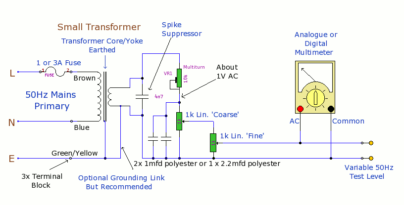
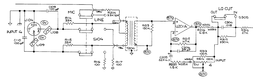
The purpose of this prototype unit is to eliminate the need for an oscillator. It provides a mains-derived and fully variable 50 Hz AC voltage, adjustable down to millivolts for comparison and accuracy testing of two or more parallel-connected...
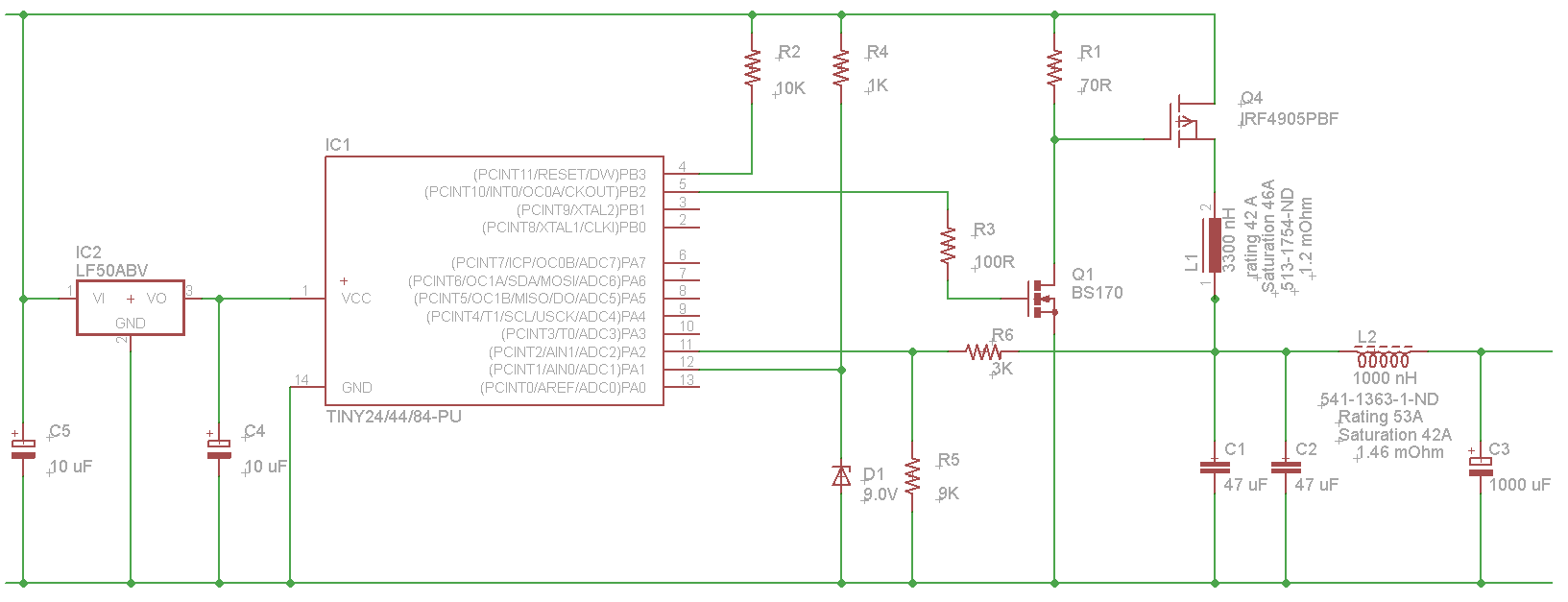
The microcontroller will not be able to drive the gate of Q1 effectively, as GPIO pins typically can only source a few milliamps, resulting in slow turn-on and turn-off times. This limitation will affect the performance of the high-side...
A popular project among microcontroller enthusiasts is to construct a radio-controlled clock. Compact receiver boards are available, equipped with a pre-tuned ferrite antenna, which can receive and demodulate the DCF77 time signal broadcast from Mainflingen, Germany. The DCF77 signal...
This timer is designed to automatically switch off a portable radio after a set period, allowing users to relax without worrying about battery drain. Resistor R1 and capacitor C1 create a long time constant. When switch P2 is momentarily...
A student is working on a project related to active electronics as part of their second year in a bachelor's program in audio production. Active electronics refers to electronic circuits that require an external power source to operate, typically involving...
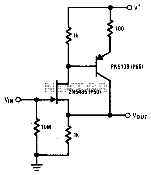
The 2N5485 features low input capacitance, making this compound series-feedback buffer a wide-band unity gain amplifier. The 2N5485 is a field-effect transistor (FET) that is often utilized in applications requiring low noise and high input impedance. Its low input capacitance...
Warning: include(partials/cookie-banner.php): Failed to open stream: Permission denied in /var/www/html/nextgr/view-circuit.php on line 713
Warning: include(): Failed opening 'partials/cookie-banner.php' for inclusion (include_path='.:/usr/share/php') in /var/www/html/nextgr/view-circuit.php on line 713