
100W AM Valve RF Transmitter circuit
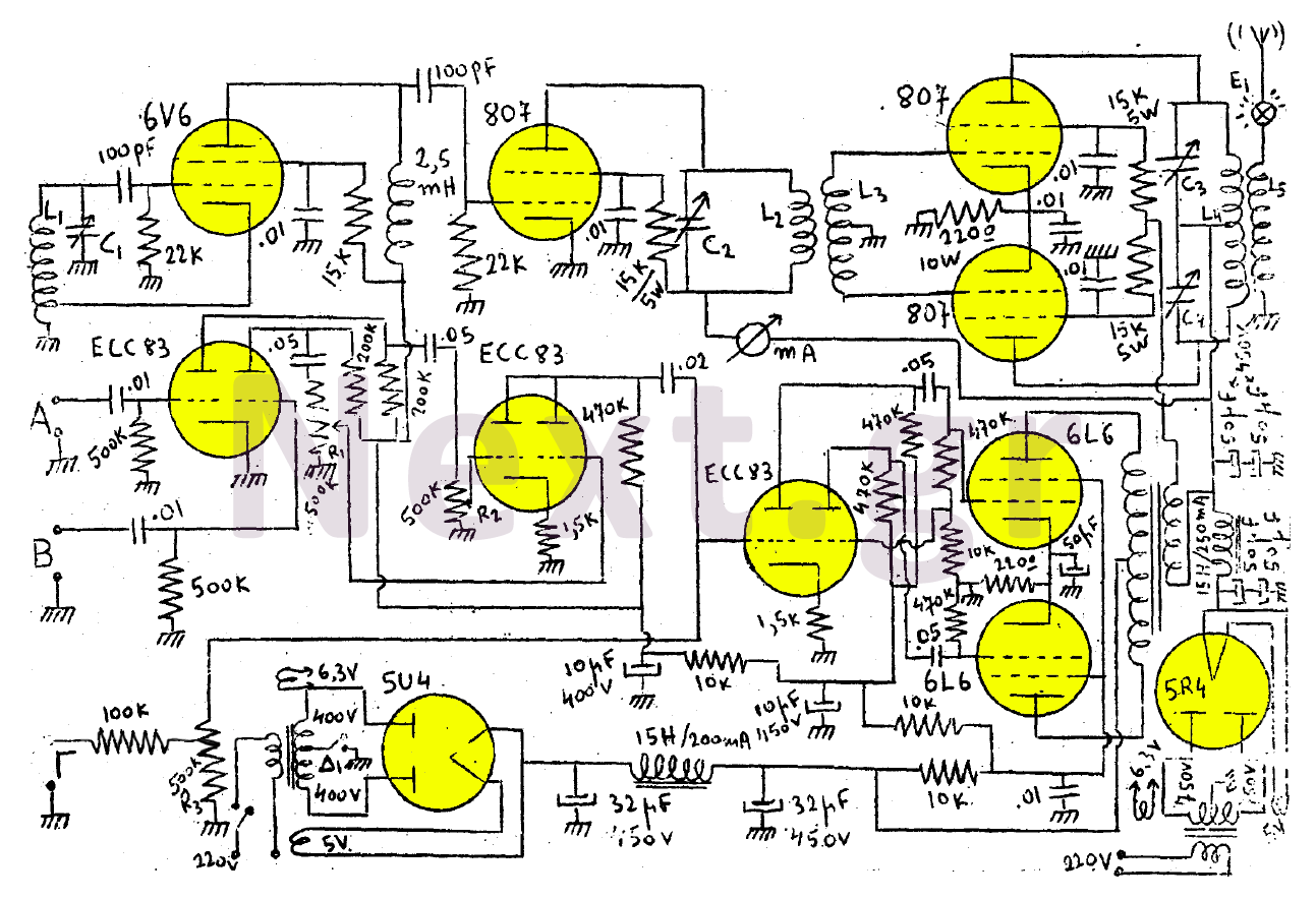
The coils L2 and L3, as depicted in the schematic, are inductively coupled. Coil L3 is constructed by wrapping 140 turns of 0.5 mm enamelled copper wire around a 5 cm cylinder. A medium shot is placed on 70 turns, which is then grounded. Coil L2 is formed by wrapping an additional 50 turns of 0.5 mm wire over the layer of L3. The variable air capacitor C2, also rated at 1000pF, must be insulated from the chassis due to the high voltage present in both coils. Coils L4 and L5 are similarly inductively coupled. Coil L5 is made by winding 100 turns of 1 mm enamelled copper wire around an 8 cm diameter form, while L4 consists of 70 loosely wound turns of the same wire, with a medium T coil placed at the 50th turn.
Variable capacitors C3 and C4 are double coaxial air capacitors, each rated at 500pF, designed with sparse plates to prevent arcing. These capacitors must also be isolated from the chassis due to high voltage concerns. An E1 indicator lamp is utilized for antenna tuning. The low-frequency amplifier has three inputs for a microphone and two other audio sources. The R2 potentiometer adjusts the volume for audio inputs A and B, while R1 and R2 (if employed) facilitate mixing. The transformer features a primary to secondary ratio of 2 and can handle a primary current of 80mA. The protective grid configuration includes a secondary modulation transformer.
For loudspeaker applications, the transmitter's amplifier can utilize an AD9047 transformer from PHILIPS, suitable for loudspeakers, despite its low secondary impedance of 16Ω. The power supply using the 5U4 tube powers the entire amplifier and the 6V6 oscillator, with a transformer specification of 220V primary and 2 x 400V secondary for 200mA, along with 6.3V and 5V outputs. The 5R4 power supply feeds the BUFFER 807 and the additional two 807 tubes, with a primary of 220V and a secondary of 2 x 750V for 250mA, as well as 6.3V and 5V outputs. A switch (D1) allows for toggling between broadcast and reception modes. This transmitter, when paired with an appropriately long antenna, can achieve significant transmission distances.This transmitter, as shown in the drawing, consists of a 6V6 as an oscillator, then the signal excites an 807 which acts as a buffer. The final step consists of two 807 in Push-Pull. The amplifier consists of three in series double-triodes ECC83 and finally two 6L6 in Push-Pull. The transmitter uses two power supplies, which is why we use two more lamps to manufacture, 5U4 kai thn 5R4.
The L1 coil will be purchased commercially as a 6sa7 medium wave oscillator. Variable C1 is 1000pF in order to be able to coordinate the transmitter across the entire range of medium waves.
The coils L2 and L3 as shown in the drawing are inductively coupled and are constructed as follows. On a 5 centimeter cylinder, wrap 140 coils with 0.5 millimeter enamelled copper wire, which will form the L3 coil. On 70 coils we place a medium shot and then ground it. Then, over the layer of L2, wrap with 0.5 mm thick wire, 50 coils that will form the L2 coil. The variable air capacitor C2 is 1000pF and must be isolated from the chassis because both reinforcements are of high voltage as shown in the figure.
The coils L4 and L5 are also inductively coupled and manufactured as follows. On a 8 centimeter diameter roller, wound with 1 mm diameter enamelled copper wire, 70 coils a little sparse with each other. This coil is L5 wrap 100 spools with 1 mm diameter wire. In the 50th coil we place a middle T coil. This is the L4.
The variable capacitors C3 and C4 are a double coaxial air (500 + 500pF) with sparse sheets to avoid sparks.
We need to isolate it from the chassis because it has a high voltage in both armatures. An E1 indicator lamp is used in order to be tuned in to the antenna. The low-frequency amplifier has three inputs (for both microphone and two other audio sources). The R2 potentiometer serves to adjust the volume of the voice or music of inputs A and B. R1 and R2 (if used) are the mixing system. The transformer has a primary to secondary ratio of 2. The primary resists up to 80mA. The configuration is made by the protective grid with its secondary modulation transformer.
If the transmitter amplifier is used to receive loudspeakers then use the Transformer with Data (AD9047 from PHILIPS) for a loudspeaker transformer. If you want, you can use this transformer to configure the transmitter despite all the few ohms that it has on the secondary (16Ω).
The power supply that uses the 5U4 feeds the entire amplifier and the 6V6 oscillator.
Its transformer is: primary 220V, secondary 2 x 400V for 200mA, 6.3V and 5V. The power supply that uses the 5R4 feeds the BUFFER 807 and the other two 807. This power adapter is: primary 220V, secondary 2 x 750V for 250mA, 6.3V, 5V. Switch D1 serves to move from broadcast to reception and vice versa. This transmitter with a good antenna (mostly long in length) can be heard too far.
Related Circuits
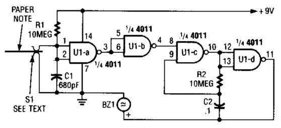
This device prevents paper notes and memos from being overlooked. A paper note placed between two fingers made of a conducting material (metal or conductive plastic) breaks the circuit, allowing pair 1 of Ul-a to go high. The goal...
The automatic sprinkler controller circuit consists of a power supply circuit and a humidity measurement and control circuit, as illustrated in the accompanying figure. The power supply circuit includes a power transformer (T), rectifier diodes (VD1 to VD4), filter...
The video master comprises a series of converters that allocate all video sources to unused UHF channels. These channels are then combined with standard TV channels, whether terrestrial or cable, into a single cable. This single cable can subsequently...
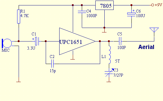
This FM transmitter is built with UPC1651, which is a silicon monolithic integrated circuit specifically designed as a wideband amplifier covering the HF band. The UPC1651 is a versatile integrated circuit that serves as a key component in FM transmitter...
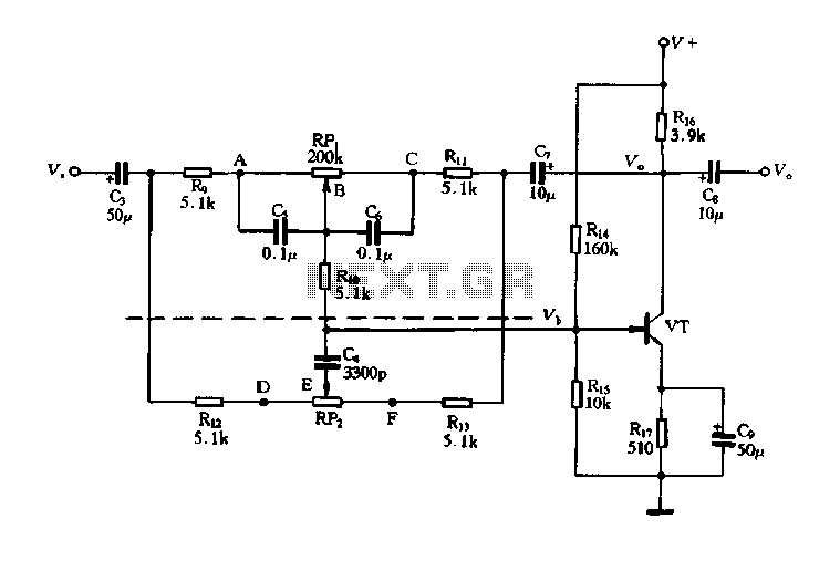
The circuit is a decay feedback tone control circuit that incorporates anti-attenuation feedback action. Its primary function is to enhance or attenuate bass frequencies, although this distinction can sometimes be challenging to perceive. The analysis utilizes the superposition theorem,...
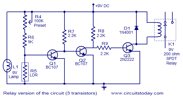
This document describes a simple fire alarm circuit utilizing a Light Dependent Resistor (LDR) and lamp combination for fire detection. The alarm activates by detecting smoke generated during a fire. When smoke is present, the circuit triggers an audible...
Warning: include(partials/cookie-banner.php): Failed to open stream: Permission denied in /var/www/html/nextgr/view-circuit.php on line 713
Warning: include(): Failed opening 'partials/cookie-banner.php' for inclusion (include_path='.:/usr/share/php') in /var/www/html/nextgr/view-circuit.php on line 713