
Automatic sprinkler controller circuit diagram 5
The automatic sprinkler controller circuit is designed to efficiently manage irrigation based on soil moisture levels. The power supply section converts the AC voltage from the mains to a regulated DC voltage suitable for powering the control circuitry. The transformer steps down the voltage, while the rectifier diodes convert the AC signal to DC. The filter capacitors smooth out the rectified output to reduce voltage ripple, ensuring stable operation of the integrated regulators.
The integrated regulators (IC1, IC2) provide the necessary voltage levels for the microcontroller and other components within the circuit. The humidity measurement section typically employs a moisture sensor that detects the soil moisture content. The sensor outputs a voltage signal proportional to the moisture level, which is then fed into an analog-to-digital converter (ADC) integrated within a microcontroller.
The microcontroller processes the ADC output and compares it against predefined moisture thresholds. If the soil is found to be dry, the microcontroller activates the sprinkler system by energizing a relay or a transistor switch connected to the water supply. Conversely, if the soil moisture is adequate, the microcontroller maintains the sprinkler system in an off state, conserving water and preventing over-irrigation.
This circuit can be enhanced with additional features such as a timer function, manual override options, or integration with weather data to optimize irrigation schedules. The overall design emphasizes energy efficiency, reliability, and adaptability to varying environmental conditions, making it suitable for both residential and agricultural applications.The automatic sprinkler controller circuit is composed of the power supply circuit and humidity measurement and control circuit, and the circuit is shown as the Figure. Power supply circuit is composed of the power transformer T, rectifier diodes VD1 ~ VD4, filter capacitors C1 ~ C3 and three-terminal integrated regulators ICl, IC2 and so on.
Humidity measur.. 🔗 External reference
Related Circuits
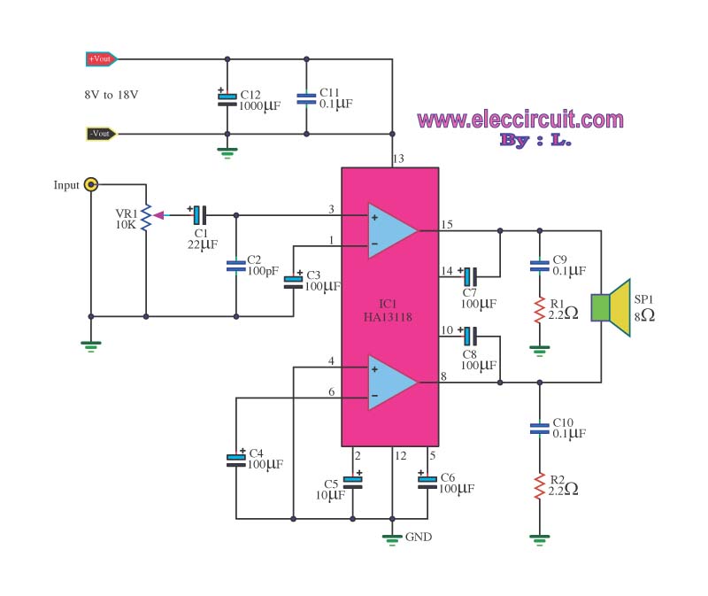
The amplifier circuit utilizes the HA13118 IC, a Hitachi component designed to deliver 18 watts of output power. This integrated circuit operates as a Class AB amplifier. The HA13118 IC is a versatile audio amplifier designed for high-fidelity applications, providing...
The paraphase configuration is noteworthy for its ability to adjust either treble or bass, but not both simultaneously. The adjustments made to the tone controls directly influence the slope of the frequency response and the extent of bass and...
The metronome circuit has been assembled multiple times without success. Two manufacturers of the 555 timer, ON Semiconductor and National Semiconductor, provide circuit designs that differ from the original. In their designs, pins 2, 6, and 7 are not...
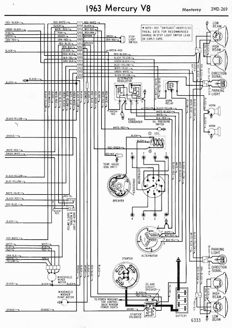
This document presents the wiring diagram for the 1963 Mercury V8 Monterey, specifically focusing on the right side of the diagram. The left side of the wiring diagram has been previously detailed. The right side diagram provides a clear...
These circuits could be used as the basis for Model Railroad DCC Boosters or PWM motor controllers. The first schematic is for a basic 3 Amp - DCC Booster using the LMD 18200 CMOS, H-Bridge. Included in the design...
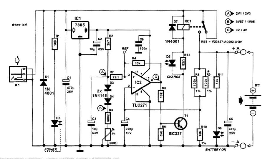
An automatic battery charger initiates the charging process when the battery voltage falls below a specified threshold and ceases charging once the voltage exceeds a predetermined maximum value. The setup is straightforward; simply connect two alligator clips to the...
Warning: include(partials/cookie-banner.php): Failed to open stream: Permission denied in /var/www/html/nextgr/view-circuit.php on line 713
Warning: include(): Failed opening 'partials/cookie-banner.php' for inclusion (include_path='.:/usr/share/php') in /var/www/html/nextgr/view-circuit.php on line 713