
10A High power led driver circuit design using LM3434
The LM3434 is designed to drive high-power LEDs efficiently, making it suitable for various lighting applications. The architecture of the LM3434 allows for a compact design, as it can operate without an output capacitor, which reduces the size and complexity of the circuit. The device's ability to maintain low ripple current is crucial for preserving the longevity and performance of the LEDs.
The two control inputs for brightness modulation enable flexibility in design. The analog current control input allows for fine-tuning of the output current, accommodating variations in LED characteristics that may arise from different manufacturing processes or to achieve desired color temperatures. This feature is particularly useful in applications where uniformity in brightness and color is essential.
The PWM functionality provides a means to control the brightness of the LEDs without causing flicker, which is often a concern in LED applications. By employing a parallel switch to short the LED during the off cycle of the PWM signal, the circuit can achieve high dimming frequencies, which are ideal for applications requiring rapid changes in brightness or color.
Safety features such as thermal shutdown and under-voltage lockout are critical for protecting both the driver and the LEDs from conditions that could lead to failure. The logic-level shutdown mode adds an additional layer of control, allowing the circuit to be easily integrated into larger systems.
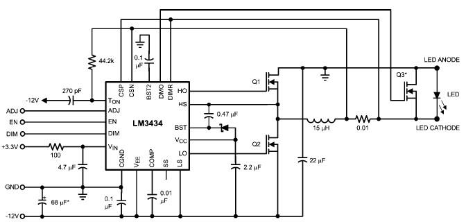
The choice of MOSFETs in the design is essential for achieving the desired performance. The mentioned MOSFETs are capable of handling the high currents required by the LEDs while ensuring efficient operation. Proper selection of these components, along with careful layout considerations, will contribute to the overall reliability and effectiveness of the LED driver circuit.Using the LM3434 adaptive constant on-time DC/DC buck (step-down) constant current controller can be designed a very simple high power led driver application. The LM3434 provides a constant current for illuminating high power LEDs. The output configuration allows the anodes of multiple LEDs to be tied directly to the ground referenced chassis for
maximum heat sink efficacy. The high frequency capable architecture allows the use of small external passive components and no output capacitor while maintaining low LED ripple current. Two control inputs are used to modulate LED brightness. An analog current control input is provided so the LM3434 can be adjusted to compensate for LED manufacturing variations and/or color temperature correction.
As you can see in the schematic circuit this high power LED driver circuit require few external components and can provide a maximum output current of 10 amperes. The PWM functions by shorting out the LED with a parallel switch allowing high PWM dimming frequencies.
High frequency PWM dimming allows digital color temperature control, interference blanking, field sequential illumination, and brightness control. Some additional features of this high LED driver project include thermal shutdown, VCC under-voltage lockout, and logic level shutdown mode.
For this power supply project you need to use a logic power supply 3. 3 volts typically and a dual 12 volts ( plus, minus 12 volts ) for powering the driver. For this power LED driver circuit diagram you can use some MOSFETs transistors like : Si7386DP, Si7668ADP, Si7790DP, NTMFS4841NHT1G or other similar types. 🔗 External reference
Related Circuits

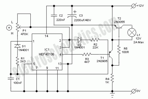
This circuit is designed to convert continuously lit lamps into flashing lights. It can be easily integrated into an existing circuit by inserting it between the lamp and the negative supply. It is particularly suitable for use with car...

Three power levels are provided by the two logic inputs of this enhanced circuit. R5, D4, D5, and O2 create a power supply for the logic integrated circuit. These components can be excluded if an alternative low voltage source...
This electronic lighting dimmer circuit is designed to control the brightness of incandescent lamps, but it is not suitable for fluorescent lamps. It operates with both 110V and 220V AC power sources. The circuit is connected in series with...
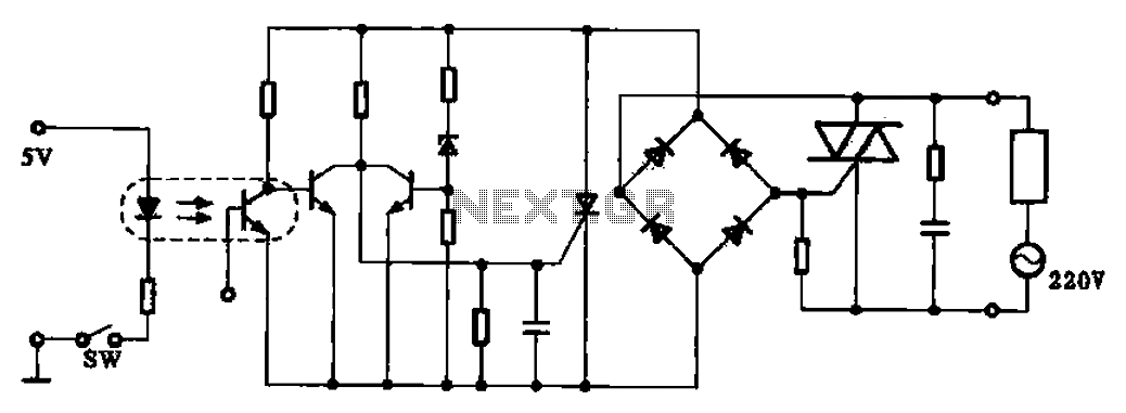
This application example illustrates a photovoltaic control circuit. In this circuit, the Triac functions as a solid-state relay, providing an AC power supply path to the load. It is designed to achieve high current control signals using a small...
This circuit utilizes an LM339 quad voltage comparator to create a time delay and manage a high current output at low voltage levels. Approximately 5 amps of current can be achieved using two fresh alkaline D batteries. Three of...
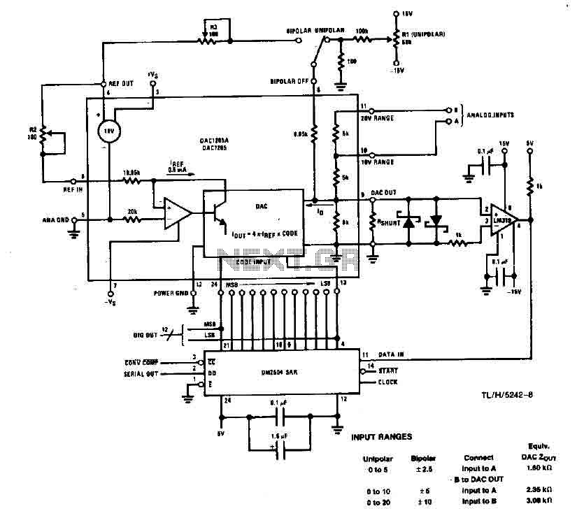
This system performs a complete conversion of 12 bits in both unipolar and bipolar modes. The converter is accurate to ±12-bit LSB with a typical gain temperature coefficient of 10 ppm/°C. In unipolar mode, the system operates within a...