
Three-Power-Level Triac Controller Circuit

This circuit is designed to operate with enhanced flexibility by utilizing two logic inputs to generate three distinct power levels. The resistors and diodes (R5, D4, D5, and O2) function collectively to establish a stable power supply for the logic integrated circuit (IC).
R5 acts as a current-limiting resistor, ensuring that the diodes D4 and D5 operate within their safe current ratings. These diodes are crucial for voltage regulation and protection against reverse polarity, which could damage the logic IC. The presence of O2, presumably another passive component such as a capacitor or inductor, further stabilizes the power supply by filtering out noise and providing a more consistent voltage level.
In scenarios where an alternative low voltage source is available, the components R5, D4, D5, and O2 can be omitted to streamline the circuit design. This feature enhances the circuit's versatility, allowing it to adapt to different power supply configurations without compromising performance.
Overall, this circuit exemplifies efficient design principles in electronic engineering, focusing on power management and component selection to optimize functionality while maintaining the potential for customization based on available resources. Three power levels are supplied by the two logic inputs of this enhanced circuit. R5, D4, D5, and 02 form a power supply for the logic IC. They can be omitted if another source of low voltage is available.
Related Circuits

Discharge before memory circuit. Before the memory circuit is activated, a delay reset circuit is required. When the input signal triggers an action, timing begins, and after a specified delay, the circuit reverts to its original state. During this...
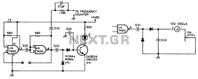
This circuit checks a crystal for activity. Two sections of a 7400 IC act as an oscillator, and its output is rectified to drive an NPN transistor that switches an LED. In an alternative configuration, a meter replaces the...
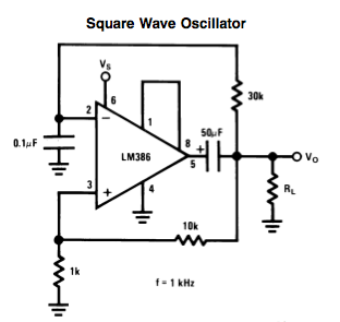
Here is a small LM386-based square-wave oscillator constructed from the following schematic. A 50k potentiometer was used in place of a 30k resistor, which functions as a pitch controller. The audio provided consists of track recordings made in Ableton...
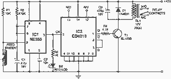
Here is an interesting circuit for a magnetic proximity switch which can be used in various applications. The magnetic proximity switch circuit, in principle, consists of a reed switch at its heart. When a magnet is brought in the...

The field scanning circuit generates sawtooth waveforms essential for color television field scanning. The circuit, as illustrated in Figure 1, is utilized in the Toshiba 2150 TV. The vertical scan pulse signal is produced from the LA7837 integrated circuit,...
The LM35 temperature sensor outputs 10 mV/C for each degree Celsius above 0°C. At 20°C, the output voltage is calculated as 20 × 10 = 200 mV. The circuit consumes minimal power. Additionally, the load resistance should not be...