
Led or Lamp Flasher Circuit

The circuit operates by utilizing a timing mechanism, typically involving a 555 timer IC configured in astable mode, which generates a square wave signal. This signal is used to control a transistor or a MOSFET that acts as a switch for the lamp. When the circuit is powered, the 555 timer oscillates, turning the lamp on and off at a predetermined frequency, thus creating the flashing effect.
The circuit can be powered by a standard 12V supply, making it ideal for automotive applications. The timing frequency can be adjusted by changing the resistor and capacitor values connected to the 555 timer, allowing for customization of the flashing rate to suit specific requirements. Additionally, the circuit may include a diode to protect against back EMF if inductive loads are used, ensuring reliability and longevity.
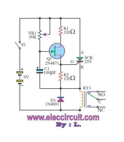
The implementation of this circuit is straightforward, requiring minimal components: a 555 timer IC, a few resistors, capacitors, and a switching device (transistor or MOSFET). The overall design is compact, making it easy to integrate into various applications without substantial modifications to existing wiring. This versatility makes it a valuable addition to automotive lighting systems, enhancing visibility and safety through the use of flashing indicators.This circuit was designed to provide that continuous light lamps already wired into a circuit, become flashing. Simply insert the circuit between existing lamp and negative supply. Especially suited for car or panel pilot lights, this device can drive lamps up to 10W.. 🔗 External reference
Related Circuits
This circuit prevents surges caused by power failures or interruptions, protecting electrical appliances from damage. It automatically switches to a short circuit mode when necessary. The surge protection circuit is designed to safeguard sensitive electronic devices from voltage spikes that...
A rear fog lamp is mandatory for trailers and caravans to enhance visibility during foggy conditions. When the fog lamp is activated, the fog lamp of the towing vehicle must be turned off to prevent distracting reflections. To achieve...
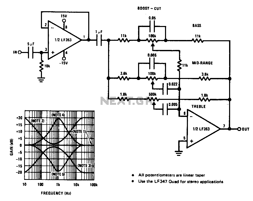
A simple single-transistor circuit provides an approximate 15 dB boost at 100 Hz and a 15 dB cut at 15 kHz. A low-noise audio transistor is utilized, and the output can be directly connected to any existing amplifier volume...
This circuit is a diagram of a mini amplifier. The amplifier circuit has a power output of 10 watts and is well-suited for car audio applications. It utilizes the TDA2009A integrated circuit as the power amplifier. To prevent excessive...
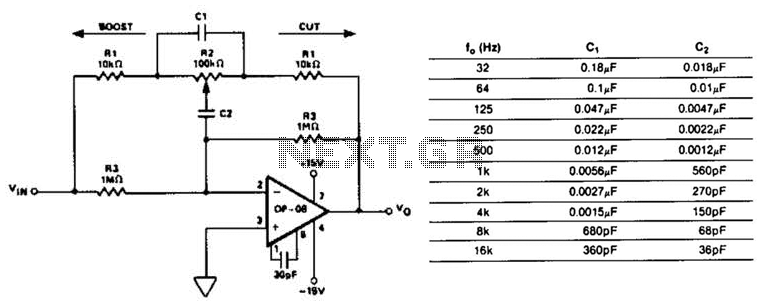
This circuit represents a section of an octave equalizer utilized in audio systems. The table outlines the values of C1 and C2 required to achieve specific center frequencies. This circuit can provide a boost or cut of 12 dB,...

The MAX2740 is a complete GPS receiver down converter chip that processes the signal from the antenna to the input of digital signal processing. The receiver channel of the MAX2740 includes a low-noise amplifier (LNA), a downconverter, a variable...