
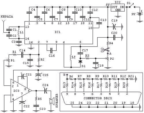
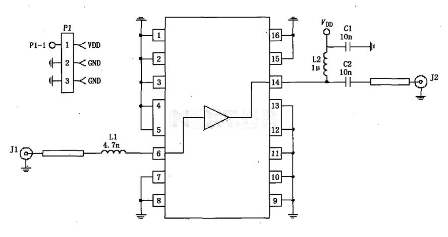
10GHz waveguide detector circuit diagram for amateur radio

The 10 GHz amateur radio waveguide detector is designed to operate within the microwave frequency range, specifically targeting the 10 GHz band commonly used in various amateur radio applications. The detector's primary function is to identify and measure radio frequency signals, providing valuable data for signal analysis and experimentation.
The waveguide structure is essential for guiding microwave signals with minimal loss. It typically consists of a rectangular or circular cross-section that confines the electromagnetic waves, allowing for efficient transmission. In this design, the waveguide is coupled to a detector element, which may be a diode or a similar semiconductor device capable of rectifying the microwave signals.
Key components of the circuit include a waveguide input, a detector diode, a low-pass filter, and an output stage. The waveguide input receives the incoming microwave signals, directing them towards the detector diode. The diode converts the high-frequency AC signals into a lower frequency DC voltage, which can be measured using a voltmeter or an oscilloscope.
The low-pass filter is integrated to eliminate any high-frequency noise that may interfere with the accurate measurement of the signal. This ensures that only the desired frequency components are processed. The output stage may include amplification circuitry to enhance the signal strength for better readability on measurement devices.
In summary, the 10 GHz frequency amateur radio waveguide detector is a crucial tool for radio amateurs and engineers working within the microwave spectrum, facilitating the exploration and understanding of high-frequency radio communications. As shown it is one for the 10GHz frequency amateur radio waveguide detector.
Related Circuits
A collection of guitar fuzz, preamp, and operational amplifier (op-amp) electronic circuits and schematics designed for various guitar effects and distortion effects. This compilation includes a diverse range of electronic circuits that cater to guitarists seeking to enhance their sound...
This circuit illustrates a Go-No/Go Tester Circuit utilizing a 555 Timer IC. Features include a more advanced unit with a precise timed testing procedure. The Go-No/Go Tester Circuit is designed to evaluate components or assemblies by providing a simple pass/fail...
Stabilised tendency of catering: Vcc=9~12V. Frequency of reception: 88~108MHz. Consumption: 100mA. If you know some language of programming as C++, PASCAL, VISUAL BASIC, DELPHI etc you can write a program which will send in the parallel door (378 I)...
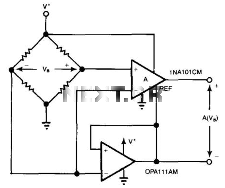
For systems with a single power supply, two operational amplifiers function as instrumentation and buffer amplifiers. The OPA111 AM buffers the reference mode of the bridge and applies that voltage to the reference terminal of the instrumentation amplifiers. The...
The wire connected to the 5V pin is linked to the positive pins of the breadboard, which are not connected to any other components. There are no additional connections on the positive column. While this may seem like a...
A 50-ohm impedance is illustrated in the RF2320 linear amplifier circuit, which is configured for input and output using transmission lines and inductive or capacitive components to create a matching network. The RF2320 linear amplifier circuit is designed to operate...