
Guitar Circuits Amps and Effects
This compilation includes a diverse range of electronic circuits that cater to guitarists seeking to enhance their sound with fuzz, distortion, and preamplification effects. Each circuit is designed to modify the audio signal in unique ways, allowing for a wide array of tonal possibilities.
1. **Guitar Fuzz Circuits**: Fuzz circuits are known for their ability to create a rich, saturated sound that adds warmth and character to guitar tones. Common designs include the classic Fuzz Face, which utilizes transistors to achieve its signature sound, and the Big Muff, known for its sustain and harmonically rich distortion. These circuits typically consist of a gain stage, followed by clipping diodes that produce the desired fuzz effect.
2. **Preamp Circuits**: Preamp circuits serve to boost the guitar signal to line level, making them essential for driving amplifiers or effects pedals. They can be designed using op-amps or discrete transistor configurations. A common approach is to use an op-amp in a non-inverting configuration, providing high input impedance and low output impedance, which preserves the tone of the guitar while amplifying the signal.
3. **Operational Amplifier (Op-Amp) Circuits**: Op-amps are versatile components that can be used in various configurations to achieve different effects. They can be employed in filters, mixers, and gain stages. For example, an op-amp can be configured as a low-pass filter to remove high-frequency noise, or as a summing amplifier to combine multiple signals. Utilizing feedback and gain control, op-amps can shape the audio signal in numerous ways, making them invaluable in the design of guitar effects.
4. **Distortion Effects**: Distortion circuits generally combine elements of fuzz and overdrive to create a more aggressive sound. They often incorporate both clipping diodes and gain stages to achieve a range of distortion characteristics, from subtle warmth to heavy saturation. Popular designs include the Tube Screamer, which utilizes op-amps to emulate the warmth of a tube amplifier.
These circuits can be implemented on printed circuit boards (PCBs) or breadboards for prototyping. Each schematic typically includes component values, pin configurations, and layout guidelines to assist in the construction process. Comprehensive knowledge of electronic components, soldering techniques, and circuit analysis is essential for successful implementation and troubleshooting of these guitar effects circuits.List of Guitar Fuzz, PreAmp, OpAmp electronic circuits and electronic schematics for a variety of Guitar effects and distortion fx.. 🔗 External reference
Related Circuits
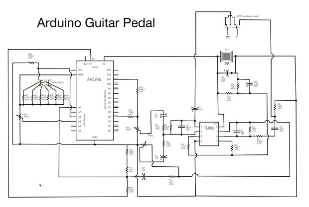
Begin constructing the circuit as illustrated in the schematic. To view the schematic in a larger format, click the small "i" icon located in the upper right corner of the image. The schematic serves as a visual representation of the...
This circuit utilizes a single 555 Timer IC along with a small transformer to generate high voltage for testing zener diodes with voltage ratings up to 50VDC. The 555 timer operates in astable mode, with the output from pin...

Below 10 MHz, the development of engineering models is relatively straightforward and not significantly influenced by printed circuit board layout. In the VHF range, parasitic circuit elements and unwanted coupling can severely impact efforts to achieve cost-effective performance without...
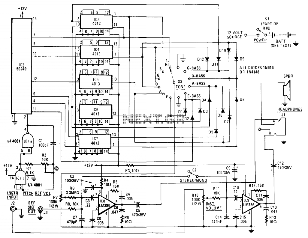
The core component of the circuit is IC2, a 50240 top-octave generator. This device utilizes a single input frequency to produce all twelve notes of the musical scale. The input signal is supplied by IC1, a 4001 quad 2-input...
The core component of this circuit is the 555 timer IC. The alert sound does not stop immediately when the switch is activated; instead, it ceases automatically after a predetermined time period, which is set by the resistance of...

The motion sensor circuit depicted in Figure 1 operates when a 12-volt power supply is applied to the input point. The motion sensor circuit is designed to detect movement and trigger a response based on the presence of motion...