
10W Audio Amplifier With Bass-Boost

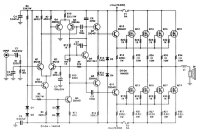
The 18 Watt audio amplifier design employs the NE5532 dual IC, which is well-regarded for its low noise and high performance in audio applications. This amplifier circuit is configured to deliver a power output that is constrained by the ±18V supply rails, ensuring that the output remains within the specified range of 9.5 to 11.5 watts. The incorporation of a bass-boost control within the feedback loop is a strategic enhancement that allows for improved low-frequency response, which is often lacking in amplifiers driving small loudspeakers. This control facilitates a maximum bass lift of +16.4 dB at 50 Hz, providing users with the ability to tailor the audio output to their preferences.
The frequency response characteristics of this amplifier are noteworthy, as they reveal a gradual increase in output even when the bass control is minimized. The amplifier demonstrates a +0.8 dB increase at 400 Hz, a +4.7 dB increase at 100 Hz, and a +6 dB increase at 50 Hz when referenced to a standard 1 kHz signal. These attributes contribute to a well-rounded audio experience, making the amplifier suitable for various applications, including home audio systems and small public address systems.
Furthermore, the design emphasizes the importance of proper grounding to mitigate potential issues such as hum and ground loops, which can adversely affect audio quality. It is recommended that all ground connections—specifically those for J1, P1, C2, C3, and C4—be consolidated at a single point to ensure a common ground reference. Additionally, connecting capacitor C9 to the output ground helps maintain signal integrity and reduces the likelihood of interference.
Overall, this amplifier design combines practical components and thoughtful engineering to deliver an effective solution for audio amplification needs, particularly in scenarios where space and component availability may be limited.This design is based on the 18 Watt Audio Amplifier, and was developed mainly to satisfy the requests of correspondents unable to locate the TLE2141C chip. It uses the widespread NE5532 Dual IC but, obviously, its power output will be comprised in the 9. 5 - 11. 5W range, as the supply rails cannot exceed ±18V. As amplifiers of this kind are freque ntly used to drive small loudspeaker cabinets, the bass frequency range is rather sacrificed. Therefore a bass-boost control was inserted in the feedback loop of the amplifier, in order to overcome this problem without quality losses. The bass lift curve can reach a maximum of +16. 4dB @ 50Hz. In any case, even when the bass control is rotated fully counterclockwise, the amplifier frequency response shows a gentle raising curve: +0.
8dB @ 400Hz, +4. 7dB @ 100Hz and +6dB @ 50Hz (referred to 1KHz). A correct grounding is very important to eliminate hum and ground loops. Connect to the same point the ground sides of J1, P1, C2, C3 &C4. Connect C9 to the output ground. 🔗 External reference
Related Circuits
This project is a 3 or more lines mixer. For more than 3 inputs you can repeat the input parts (P=10K R=22K). It powered with 9Vdc. The described project is a multi-channel audio mixer designed to handle three or more...
The circuit incorporates components Q, C, and ZD, which are responsible for the bias and buffer stages. Its primary objective is to ensure stable MOSFET gate operation and provide an offset voltage through a voltage buffer amplifier stage with...
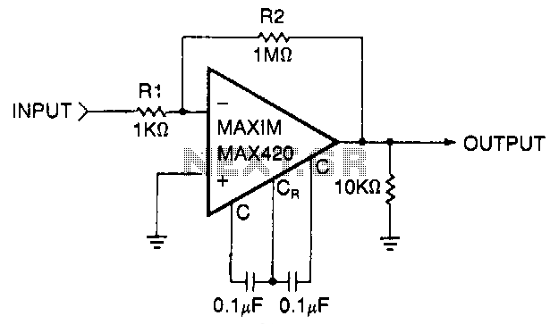
This circuit is a gain-of-1000 inverting amplifier designed to amplify submillivolt signals to levels suitable for further processing. In most system applications, utilizing maximum gain in the MAX420 is advantageous, as it minimizes the effects of offsets in later...
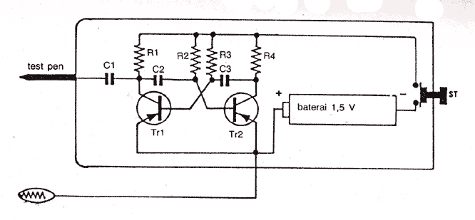
Audio Jammer Noise generator for detector audio circuit More: Parts: R1,R4 . 1K 0,5W R2,R3 . 39K 0,5W C1 . 5000pF/50V C2,C3 . 3000pF/50V FCS9012 . PNP FCS9012 . PNP The audio jammer circuit functions as a noise generator, designed...
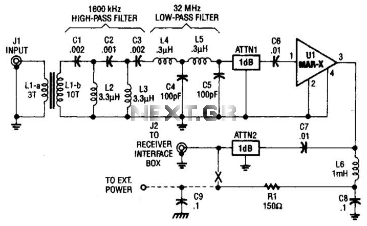
This high-frequency shortwave receiver preamplifier consists of a broadband toroidal transformer (LI-a and Ll-b), a complex LC network that includes a 1600 kHz high-pass filter and a 32 MHz low-pass filter, inductors L2 and L3 (26 turns of #26...
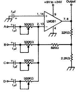
LM381 4-channel audio mixer circuit design project using a few common electronic parts. The LM381 audio mixer circuit is designed to combine audio signals from four separate channels into a single output. This circuit employs the LM381 integrated circuit, which...