
400w mosfet amplifier circuit schematic
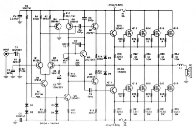
The circuit employs a combination of transistors, capacitors, and Zener diodes to establish a robust biasing and buffering mechanism essential for the operational stability of MOSFET gates. The biasing circuit is critical in maintaining the appropriate gate voltage, which directly influences the switching characteristics and overall efficiency of the MOSFETs. The inclusion of capacitors serves to filter out noise and stabilize the voltage levels, while Zener diodes provide voltage regulation, ensuring that the gate voltage remains within specified limits.
The feedback loop design is crucial for maintaining linearity and minimizing distortion. The introduction of a dominant pole is a strategic choice to enhance stability, preventing oscillations that can arise from high-frequency response. This design consideration is particularly important in high-power applications where transient response and signal integrity are paramount.
In terms of load handling, the circuit is designed to accommodate varying impedances, making it versatile for different speaker configurations. The ability to drive 2-ohm loads, albeit temporarily, showcases the amplifier's robustness. However, caution is advised against extended operation at high power levels to prevent thermal overload and potential damage to the components.
The power supply section, featuring a toroidal transformer, is optimized for efficiency and low electromagnetic interference. The transformer’s 1 kVA rating indicates its capability to handle significant power demands while maintaining stable output voltage levels. The design of the primary windings is tailored to ensure compatibility with the overall circuit, allowing for effective energy transfer and minimal losses.
Overall, this circuit design exemplifies a well-engineered approach to high-power amplification, balancing performance with reliability through careful component selection and circuit topology.As the name suggests All Q, C and ZD the Bias and buffer phases. Its main goal is to provide a stable MOSFET Gates and offset voltage and the voltage buffer amplifier stage of the High Resource capacity. What would have without the phase response and the effect Slew rate is indeed very bad. The flip side of the coin is not the extra step Introduct ion of an additional dominant pole in the amplifier feedback loop. Also to what the name suggests this stage converts the voltage developed in the VAS and provides all the amps required to drive at 8 or 4 ohms. 2-ohm loads are possible for several minutes at a time. In fact, I have tested more than 1600 1kW amplifier Watts RMS at 2 ohms. But that would not be recommended as a long-term exposure at all. If it is higher than the figures of the STI-amp. Power to the AV amplifier 800 The components of the power for this amplifier are as follows, and are favored A channel or a power module alone.
1 toroidal transformer with a rating of 1kVA. Primary windings are made to fit 🔗 External reference
Related Circuits
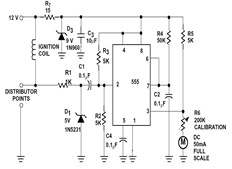
The sections available in this datasheet cover general design considerations for the 555 timer, frequently asked application questions (FAQ), design formulas, and examples of innovative applications. Examples of applications include a Missing Pulse Detector, Pulse Width Modulation (PWM), Tone...
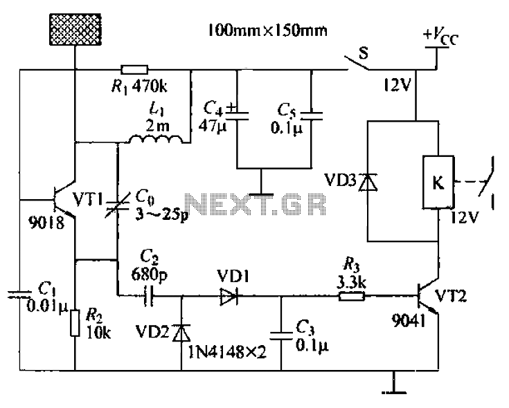
A capacitive proximity controller typically consists of a radio frequency oscillation circuit and a detection plate. The circuit is constructed using discrete components for capacitive proximity sensing detection. The transistor VT1, along with surrounding components, forms a radio frequency...
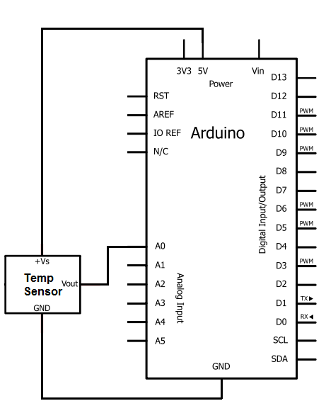
The integrated circuit (IC) used for temperature measurement is the TMP36. This IC will be integrated with an Arduino to obtain temperature readings. The Arduino will read the measured value from the TMP36 and convert it into degrees Fahrenheit,...
The automatic irrigation control circuit is designed to manage crop irrigation based on soil moisture levels. It is applicable in various agricultural settings, including state farms, orchards, vegetable greenhouses, and large farmland areas. The circuit comprises a soil moisture...
In this circuit exists a second designing proposal of preamplifier RIAA. The first stage uses discernible components and in second exist a opamp. [IC1]. In the negative feedback exist the correction RIAA filters. Certain points need certain discriminators: 1]...
The PowerSaver Flasher uses capacitive output coupling to produce brighter shorter flashes and has a much lower average current drain than standard bicore or 74HC14 flashers. The PS Flasher with one LED circuit (2 LEDs) runs all night from...