
Hf Preamplifier Circuit
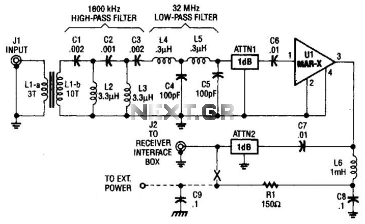
The high-frequency shortwave receiver preamplifier is designed to enhance the signal quality of incoming radio frequency signals, particularly in the shortwave spectrum. The use of a broadband toroidal transformer ensures minimal signal loss and improved performance across a wide frequency range. The transformer, labeled LI-a and Ll-b, is crucial for impedance matching and signal coupling.
The LC network integrated into the design serves a dual purpose: it filters unwanted frequencies while allowing the desired signals to pass. The 1600 kHz high-pass filter effectively attenuates low-frequency noise, while the 32 MHz low-pass filter prevents high-frequency interference from corrupting the signal. This combination ensures that the preamplifier can operate efficiently within its intended frequency range.
Inductors L2 and L3, constructed with 26 turns of #26 enameled wire on a T-50-2 toroidal core, are essential components of the LC network. The choice of wire gauge and the toroidal core material contributes to the overall efficiency and stability of the circuit, minimizing losses and enhancing the quality of the amplified signal.
The resistive attenuators, ATTN1 and ATTN2, are implemented to manage the signal levels entering the preamplifier, preventing distortion and clipping that may occur from excessively strong signals. These attenuators can be adjusted to suit the specific requirements of the application, providing flexibility in signal management.
The MAR-x device, a key component of the preamplifier, is responsible for the amplification of the received signals. Its specifications should be matched to the operational requirements of the circuit to ensure optimal performance.
Powering the preamplifier requires an external DC supply, with a voltage range of 9 to 12 V. Adjustments to the resistance value of Rl may be necessary when operating at higher voltages, allowing for fine-tuning of the circuit to achieve desired performance characteristics. This adaptability is essential for various applications, ensuring that the preamplifier can be tailored to meet specific operational needs. This HF SW receiver preamplifier is comprised of a broadband toroidal transformer (LI-a and Ll-b), a complex LC network (comprised of a 1600- kHz, high-pass filter and a 32-MHz, low-pass filter), L2 and L3 (26 turns of #26 enameled wire wound on an Amidon Associates T-50-2, red, toroidal core), a pair of resistive attenuators (ATTN1 and ATTN2), and of course, the MAR-x device. External power for the preamp can be 9 to 12 Vdc. Rl can be increased in value for liigher voltages. 🔗 External reference
Related Circuits
Equipment designed to detect changes associated with fire, monitor the integrity of their operations, and provide automatic control and transmission of information necessary to prepare the facility for fire, temperature, and light based on a predetermined sequence. The panel...
The American Electrician describes a glass battery jar measuring six inches by eight inches, wound with 60 to 80 turns of American wire gauge No. 18 B & S magnet wire. Inside this jar is a primary winding consisting...
For bikers or scooter riders, it is common to forget to cancel flashing indicators after making a turn, especially without an audible reminder. Continuously checking indicator lamps is impractical, as attention should remain focused on the road. The circuit...

The DC motor E inversion control circuit utilizes a loop configuration with various relay contacts. It employs a single set of normally open/normally closed relay contacts. When both inputs A and B are low, relay KI is activated. In...
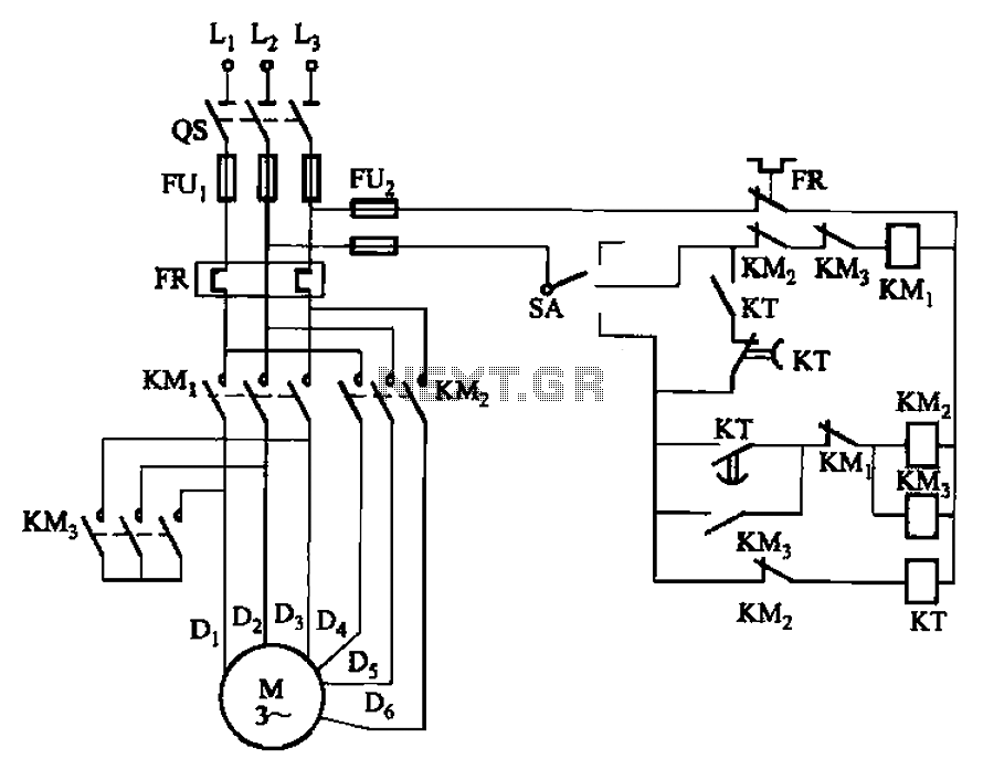
The circuit depicted in Figure 3-98 demonstrates how motor starting and low-speed operation are managed using switch SA. By adjusting the time relay KT, the motor's operation can transition from low speed to high-speed operation within a specified time...
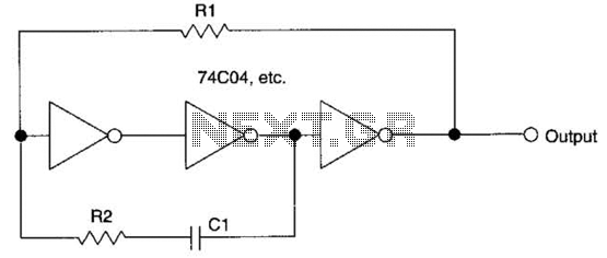
This circuit employs a protective resistor R2 along with a feedback resistor R1. Together, these components create a voltage divider that lowers the input voltage amplitude for IC1-a, ensuring that the protective diodes remain inactive. This arrangement enhances the...