
10w audio amplifier with bass

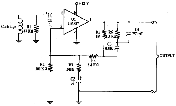
In electronic circuits, grounding serves as a reference point for all voltage levels within the system and is critical for maintaining signal integrity. Ground loops can introduce unwanted noise, often manifesting as hum in audio applications. To mitigate these issues, it is recommended that all ground connections be consolidated to a single point.
In this particular schematic, the components J1 (likely a connector), P1 (possibly a power input), and capacitors C2, C3, and C4 must share a common ground connection. This ensures that any potential differences between the ground points of these components are eliminated, reducing the likelihood of interference.
Furthermore, C9 should be connected to the output ground. This capacitor may be used for filtering purposes, smoothing out voltage fluctuations at the output, thus enhancing the overall performance of the circuit. By ensuring that C9 is grounded properly, it can effectively minimize noise and stabilize the output signal.
Overall, careful consideration of grounding practices is vital in circuit design to ensure optimal functionality and reliability.A correct grounding is very important to eliminate hum and ground loops. Connect to the same point the ground sides of J1, P1, C2, C3 &C4. Connect C9 to the output ground. 🔗 External reference
Related Circuits
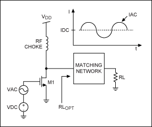
This application note provides a concise overview of power amplifier theory and presents simulation results that offer insights into the operation of the power amplifier across all of MAXIM's LFRF transmitters and transceivers. Power amplifiers are critical components in communication...
A magnetic pickup from an old record player can function effectively as a pressure and vibration sensor. By replacing the needle with a thin metal plate (copper from a PCB is suitable), an excellent touch sensor can be created....
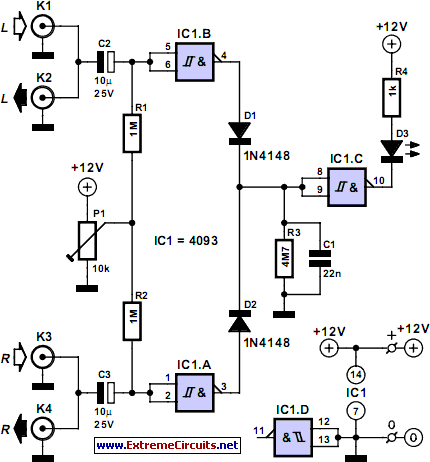
This audio peak detector enables monitoring of a pair of stereo channels using a single LED indicator. The circuit employs identical configurations for both left and right channels. It utilizes the switching levels of Schmitt trigger NAND gates within...
Assistance is sought for building the N4GG audio intelligibility enhancer project as detailed in the ARRL Handbook. A circuit board has been ordered from Far Circuits, but there are difficulties in sourcing the necessary components. Attempts have been made...
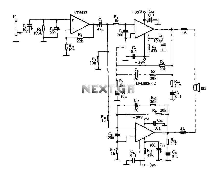
Figure 2-60 depicts a practical circuit for the LM3886 amplifier, which incorporates an NE5532 as a preamplifier, capable of delivering an output power of up to 200 Watts. Given the high output power of the LM3886 power amplifier, it...
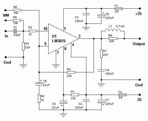
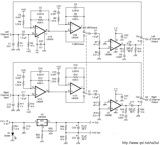
The amplifier drives a pair of speakers using two LM3876 amplifier chip circuits (50 watts per channel) or a pair of headphones with Meier Crossfeed through a clarifier and a dual OPA2134 Opamp. It features four selectable band inputs...