
audio peak detector
This audio peak detector circuit is designed to visually indicate audio signal peaks from stereo channels using a single LED. The core of the circuit is based on the 4093 IC, which contains multiple Schmitt trigger NAND gates. Each channel's signal is processed identically, ensuring consistent performance.
The threshold for detecting peaks is adjustable via the preset resistor P1. This allows for calibration based on the specific audio signal characteristics, accommodating different audio sources and levels. The high impedance bias provided by R2 (R1) allows for the audio signal to be superimposed effectively, ensuring that the Schmitt trigger gates respond appropriately to changes in the audio signal.
When the audio signal, combined with the bias voltage, causes the voltage at the input pins of the Schmitt trigger to drop below the defined threshold, the output transitions to a high state. This transition is crucial as it triggers the subsequent stages of the circuit. The output from IC1.A (IC1.B) is fed into IC1.C, which inverts the signal, thereby lighting LED D3 when a peak is detected.
The inclusion of R3 and C1 introduces a delay in the circuit, which is essential for accurately capturing short audio peaks. This delay prevents the LED from flickering due to rapid fluctuations in the audio signal, allowing for a more stable visual indication of audio peaks.
The circuit is designed for ease of use, with initial setup instructions that guide the user to adjust the threshold to ensure proper operation. By applying line-level audio to the RCA connectors, users can effectively monitor audio signals without the need for specialized splitter cables, making this circuit a practical solution for audio peak detection in various applications.This audio peak detector allows a pair of stereo channels to be monitored on a single LED. Identical circuitry is used in the left and right channels. Use is made of the switching levels of Schmitt trigger NAND gates inside the familiar 4093 IC. The threshold level for gate IC1. A (IC1. B) is set with the aid of preset P1, which supplies a high impe dance bias level via R2 (R1). When, owing to the instantaneous level of the audio signal superimposed on the bias voltage by C3 (C2), the dc level at pins 1 and 2 (5 and 6) of the Schmitt trigger gate drops below a certain level, the output of IC1. A (IC1. B) will go High. This level is copied to the input of IC1. C via D2 (D1) and due to the inverting action of IC1. C, LED D3 will light. Network R3-C1 provides some delay to enable very short audio peaks to be reliably indicated. Initially turn the wiper of P1 to the +12 V extreme ” LED D3 should remain out. Then apply line` level audio to K1 and K3, preferably music with lots of peaks (for example, drum n bass).
Carefully adjust P1 until the peaks in the music are indicated by D3. The circuit has double RCA connectors for the left and right channels to obviate the use of those rare and expensive audio splitter (Y`) cables. 🔗 External reference
Related Circuits
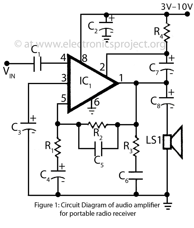
This is a simple audio amplifier circuit built around the BEL1895 1W audio amplifier integrated circuit (IC). This circuit serves as an alternative to more complex audio amplifier circuits designed for portable radio receivers. It does not require a...
The circuit topology is similar to the previously mentioned amplifier, utilizing the robust IRFP240 and IRFP9240 MOSFET devices as the output pair, along with high-voltage Motorola transistors in the preceding stages. The supply rail voltage is conservatively set at...
A 2 x 18W Hi-Fi Stereo Power Amplifier is designed using two TDA2030 integrated circuits (ICs). This amplifier features excellent input sensitivity, low distortion, robust operating stability, and comprehensive protection against overloads and output short-circuits. It is suitable for...
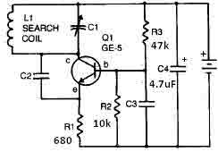
This metal detector circuit needs to be powered using a 9 volts power supply (DC) or a 9 volts battery. The C1 capacitor is a variable capacitor with a value of 365 pF, C2 is a 100 pF silver...
Parts List The circuit consists of a preamplifier, tone controls, and a regulated DC power supply, providing a power output of 18 Watts for an 8 Ohm load. The circuit design includes three main components: a preamplifier, tone control circuitry,...
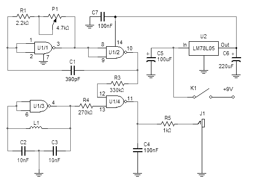
This simple metal detector requires only a handful of components and an evening's work. Built around a cmos4011 IC, is very robust and versatile. The 250 kHz reference oscillator is built with two gates (U1/1 and U1/2), C1, R1...