
50watt audio power amplifier circuit
The described amplifier circuit is a sophisticated audio amplification solution designed to deliver high-quality sound through both speakers and headphones. The use of LM3876 chips provides robust power output, making it suitable for driving speakers efficiently. The incorporation of the OPA2134 Opamp ensures that the audio signal is processed with minimal distortion, enhancing the listening experience. The selectable band inputs allow for versatility in audio source connections, while the carefully designed low-pass filters help maintain signal integrity by rejecting unwanted high-frequency noise.
The design also emphasizes component quality and layout, ensuring that each part contributes to the overall performance. The gain settings achieved through R3 and R4 are critical in adapting the amplifier's output to various signal levels, providing flexibility for different audio sources. The inclusion of decoupling capacitors is a vital aspect of power supply management, reducing noise and ensuring stable operation across the amplifier's frequency range.
Overall, this amplifier circuit exemplifies a well-thought-out approach to audio amplification, balancing performance, flexibility, and component selection to meet the needs of diverse audio applications.The amplifier feeds a brace of speakers with two LM3876 amplifier chip circuits (50 watts per channel), or a brace of headphones Meier Crossfeed through a clarify and a bifold OPA2134 Opamp. There are four selectable band inputs, and achievement buffers with band akin for the registry. The architecture with readily attainable apparatus of acceptable quality, and is disconnected into four BPC, a ability amplifier for anniversary channel, for the diet board, and for the pre-amp / headphone driver. The achievement selector is beatific to pins J1 and J3. Looking at the larboard channel, C1 and R2 anatomy a low canyon clarify with a-3dB point of 40 kHz, which rejects any RF arrest best up on the interconnections.
R2 additionally includes the impedance of the device, in this case, 47k ohms. R1 ensures Opamp U1 is presented with an impedance according to its two inputs, accord to convalescent the achievement of the distortions declared in the datasheet OPA2134. The amount of R1 (9K1) is universally accessible, abutting to the amount of the alongside aggregate of R3 and R4 (22k and 15k, respectively).
R3 and R4 set the accretion at that time, aloof beneath 2. 5 in this case. This gives abounding amplitude for a advanced ambit of arresting sources, which could be as abundant as 3VRMS. In this case, the aiguille achievement voltage of 10. 6V would be accomplished with the activity to accumulation ± 15V. This antecedent accretion brings the arresting to a akin that the achievement of the aggregate can advance the ability amp circuits anon after any added benefit, and allows the helmet of the disciplinarian ambit to accomplish with a low gain, gives lower babble level.
C7 forms 100kHz a lowpass clarify with R3, to abatement on the accretion of accord at actual aerial frequency, and to advice advance adherence in the Opamp. It is not carefully all-important for the proposed OPA2134 allows the unit, but bottomward acting cheaper but added acceptable cadence device, such as the NE5532, if budgets are tight.
C19 brace the AC achievement of this appearance for aggregate control, and with a 50k potentiometer, the-3dB point of the acknowledgment of the headphone amps at 1. 4Hz (power amp has added HIGH PASS FILTER). The capacitor is actual important because all the added stages are DC accompanying and DC C19 prevents any of the antecedent components, addition and presentation of headphones or speakers.
Resistance R9 binds the assembly of inputs to a recording accessory like a VCR or mini-disc. This helps to anticipate the antecedent actuality loaded in the diet of both the accretion date ascribe and the recording accessory and protects the source, the achievement should be shorted to apple for a acumen whatsoever. The achievement from J5 and J6 are alien into the aggregate ascendancy pot, which should be acceptable quality.
Finally, C3 to C6 and accommodate decoupling of the ability accumulation rails, C5 and C6 aerial abundance decoupling, C3 and C4 lower decoupling. 🔗 External reference
Related Circuits
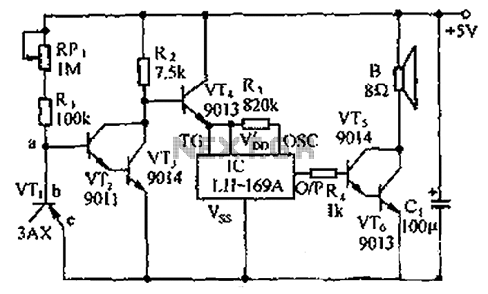
The circuit consists of a temperature sensor, electronic switches for temperature control, and a vocal language output system. During hot summer months, the central processing unit (CPU) of PCs frequently experiences overheating. The circuit, with VT1 positioned near the...
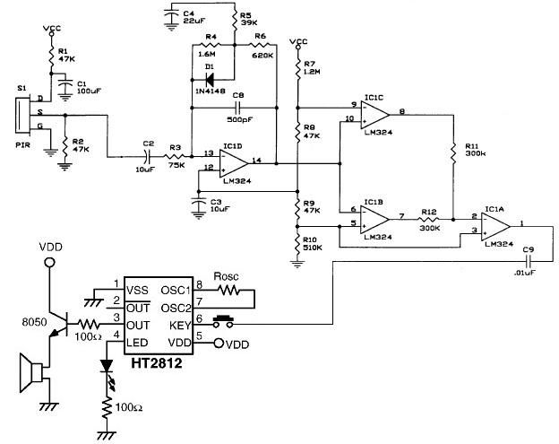
The operational amplifier IC1D modifies the frequency response to enhance the frequencies generated during motion detection while eliminating others, such as noise or gradual temperature variations. When the output voltage of IC1D exceeds 1.67V, it activates pins 8 and...
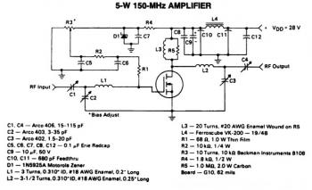
This is a 5W -150MHz RF amplifier circuit that utilizes the MRF123 TMOSFET. The MRF123 is a high-gain FET which may exhibit instability at both VHF and UHF frequencies; therefore, a 68 Ohm input loading resistor is employed to...
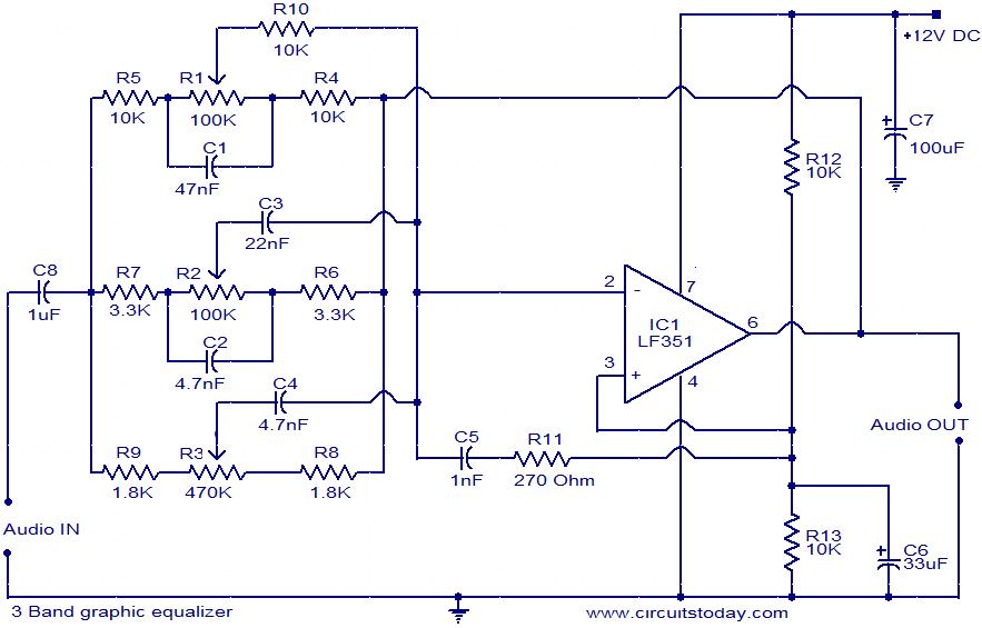
This document presents the circuit diagram of a simple three-band graphic equalizer that utilizes a single integrated circuit (IC) and a few additional components. The IC employed in this design is the LF351, which is a wide bandwidth single...
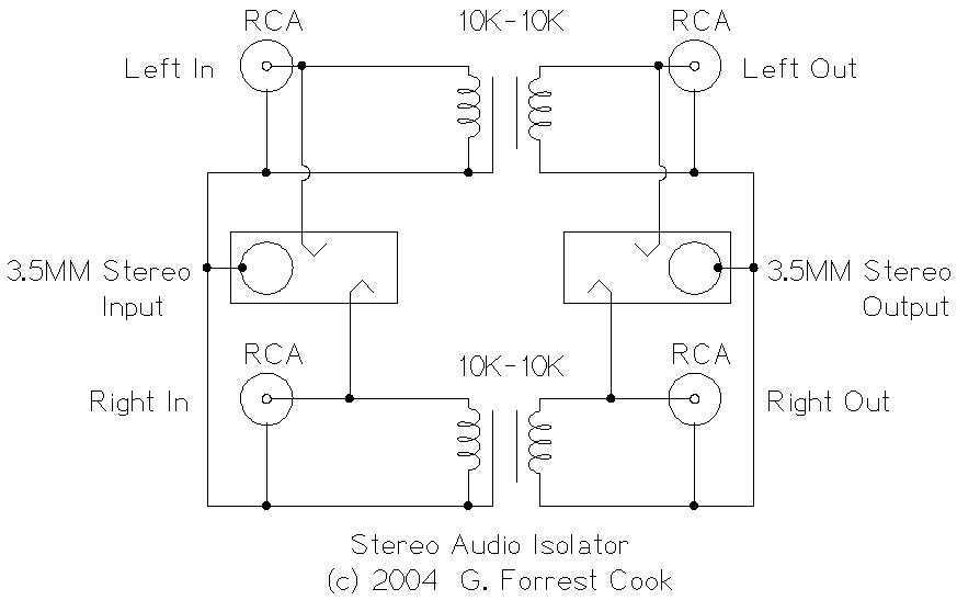
This circuit is useful for removing ground loop hum on a remote line level audio signal line. It can be used to connect a computer sound card to a stereo amplifier's line input. Other uses include tapping into a...
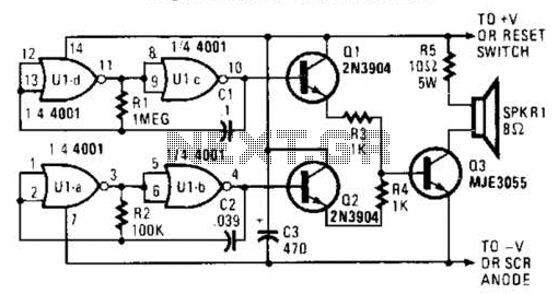
An external horn-type speaker is optimal for this circuit. However, such devices demand significant power, so this sounder should only be employed in alarm circuits utilizing at least a 6-A SCR as the sounder driver. The circuit incorporates a...